
Polo Mk4
 Note
Note
Note
|
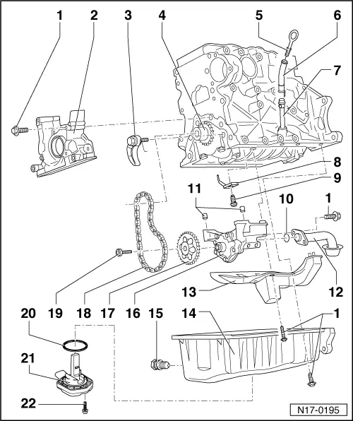
| 1 - | 15 Nm |
| 2 - | Sealing flange |
| q | With sealing ring |
| q | With silicone seal D 176 404 insert A2 → Chapter. |
| q | Remove and install → Chapter. |
| q | Do not lubricate or grease seal lip |
| q | Before installation, remove oil residues from crank shaft trunnion with a clean cloth. |
| q | Replace crank shaft seal - pulley side → Chapter and → Chapter. |
| 3 - | Chain tensor with tension rail, 15 Nm |
| q | When installing, pre-tension spring and hook it |
| 4 - | Gear |
| 5 - | Oil measuring stick |
| q | Oil level must not be over the Max. marking! |
| q | Marking → Fig., → Fig. |
| 6 - | Funnel |
| q | Remove to suck oil |
| 7 - | Guide tube |
| 8 - | Oil ejector |
| q | For piston refrigeration |
| 9 - | 25 Nm |
| q | Install without seal |
| 10 - | Sealing ring |
| q | Replace |
| 11 - | Adjusting guide |
| 12 - | Suction tube |
| q | Clean sieve if dirty |
| 13 - | Acoustic muffler |
| 14 - | Oil carter |
| q | Clean seal surface before installation |
| q | Remove and install → Chapter. |
| 15 - | Oil draining plug 30 Nm |
| q | In case of leakage, cut sealing ring and replace it |
| 16 - | Oil pump |
| q | With over pressure valve 12 bar |
| q | Before installation, check if the 2 guide bushings for centralizing oil pump/engine block are in place |
| q | Replace if there are grooves on sliding surfaces and gears |
| 17 - | Chain gear for oil pump |
| q | Mind the installation position |
| q | Only fits in one position |
| 18 - | Chain |
| 19 - | 20 Nm + 90 ° |
| 20 - | Seal |
| q | Replace |
| 21 - | Oil level and temperature sensor -G266- |
| 22 - | 10 Nm |
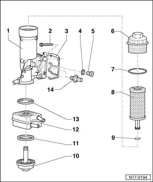
| 1 - | Oil filter support |
| 2 - | 15 Nm + 90 ° |
| q | Replace |
| q | First seat screw above left and below right, then tighten 4 cross screws |
| 3 - | Joint |
| q | Replace |
| 4 - | Seal |
| q | Replace |
| 5 - | Plug, 25 Nm |
| q | Do not loosen |
| 6 - | Draining plug, 25 Nm |
| q | Loosen and tighten with oil filter wrench 3417 |
| 7 - | Sealing ring |
| q | Replace |
| 8 - | Oil filter element |
| q | Check installation position top = above |
| 9 - | Sealing ring |
| q | Replace |
| 10 - | Draining plug, 25 Nm |
| 11 - | Joint |
| q | Replace |
| 12 - | Oil radiator |
| q | Ensure mobility in relation to surrounding components |
| q | Pay attention to note → Chapter. |
| 13 - | Joint |
| q | Replace |
| 14 - | Oil pressure sensor -F1-, 20 Nm |
| q | 0.7 bar sensor: brown |
| q | In case of leakage, cut sealing ring and replace it |
| q | Check → Chapter. |
| q | Remove and install → Chapter. |