
Polo Mk4
 WARNING
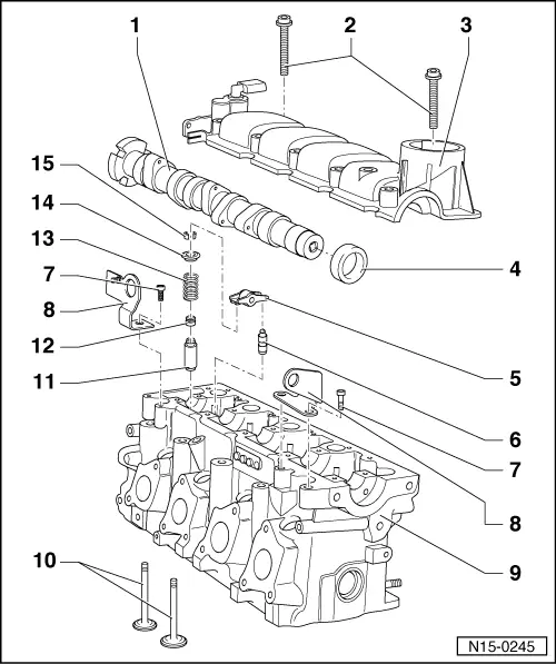
| 1 - | Camshaft |
| q | Check axial clearance → Chapter. |
| q | Removal and installation → Chapter. |
| q | Measure radial clearance using Plastigage: - limit for wear: 0.00 in. |
| q | Runout: max. 0.00 in. |
| q | Code → Fig. |
| 2 - | 6 Nm + 90° |
| q | Replace after each removal. |
| q | Observe installation and sequence instructions when loosening and tightening → Chapter. |
| 3 - | Cylinder head cover |
| q | It may not be replaced separately, only together with the cylinder head. |
| q | Sealing surfaces cannot be ground. |
| q | With integrated camshaft bearings. |
| q | Cover and head form a pair; therefore, the pair engraving is on the exhaust manifold side, close to Hall Sensor -G40-. |
| q | Remove all sealant residues. |
| q | Apply Sealing compound for engines -AMV 188 001 02- or Sealing compound for engines -D 154 103 A1- before positioning. |
| q | For assembly, place in vertical position from top with guides in cylinder head holes. |
| q | Removal and installation → Chapter. |
| 4 - | Camshaft seal |
| q | Quickly lubricate with oil the sealing ring lip. |
| q | Replace → Chapter. |
| 5 - | Rocker arms |
| q | Check free operation of the roller. |
| q | Lubricate the contact surface with oil. |
| q | For installation, loosen the safety clamp on the support element. |
| q | Supplier „INA“ with „030“ engraving on the side near the spherical region. |
| q | Supplier „GTT“ with „S3011“ engraving on the side near the spherical region. |
| q | Do not mix, as in a single head only parts from the same supplier may be installed. |
| 6 - | Support element |
| q | Do not change the working position. |
| q | With hydraulic valve clearance compensation. |
| q | Lubricate the contact surface with oil. |
| q | Supplier „INA“ with„I“ engraving on the bottom of the support element. |
| q | Supplier „GTT“ with „GT“ engraving on the bottom of the support element. |
| q | Do not mix, as in a single head only parts from the same supplier may be installed. |
| 7 - | 25 Nm |
| 8 - | Lifting tackle/eyelet |
| q | Spare part numbers: Support -030 103 390 F- (pulley side) Support -030 103 390 G- (flywheel side). |
| 9 - | Engine cylinder head |
| q | The sealing surface on the camshaft side must not be ground. |
| q | The head and the cover form a pair; therefore, the engraving for the pair is on the exhaust manifold side, close to Hall sensor -G40-. |
| q | When replacing, check printed code on the cover and cylinder head, they must be the same. |
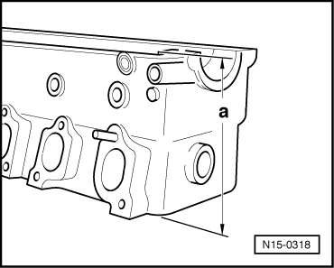
| q | Check warping → Fig. |
| q | After replacing, replace coolant. |
| q | Disassembly and assembly → Chapter. |
| q | Grind valve seat → Chapter. |
| q | Grind sealing surface on the cylinder block side → Fig. |
| 10 - | Valves |
| q | Do not grind, only seating is permitted. |
| q | Valve dimensions → Fig. |
| q | Remove with the Device -2036- and the Plate -VW 5541/3-. |
| 11 - | Valve guide |
| q | Check → Chapter. |
| 12 - | Valve stem oil seal |
| q | Replace → Chapter. |
| 13 - | Valve spring |
| q | Removal and installation with engine cylinder head removed using the Compression device -2037- → Chapter. |
| 14 - | Spring dish |
| 15 - | Keys |
 Note
Note
|
|