volkswagen Workshop Repair Guides

Volkswagen Workshop Service and Repair Manuals

Crankcase ventilation device/oil filter support - disassemble and assemble > < Valve stem sealant - replace|Installation
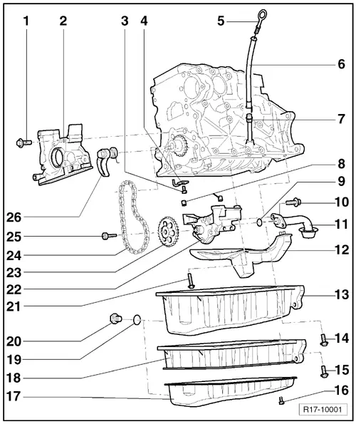
Lubrication system components - remove and install
  Note
t  If during engine repairs considerable amounts of metal filings are found, this may indicate that the crankshaft bearings or the connecting rod shells are damaged. To prevent further damage, proceed as follows:
t  Clean the lubrication channels carefully.
t  Replace the oil injector valves.
t  Replace oil radiator.
t  Replace the oil filter.
t  
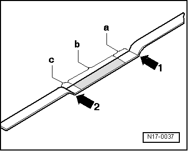
The oil level should not exceed the Max. marking - risk of damage to the catalytic converter! Markings → Fig., → Fig.
  WARNING
Always replace self-locking nuts and screws subject to angular torque.
Check the oil pressure and the Oil pressure switch -F1- → Chapter.
Oil supply volume
with oil filter 4.0 l
Engine oil specification:
Use multi-purpose oils in accordance with specification VW 501 01 or high lubrication oils in accordance with VW 502 00 for vehicles until 11/2002. From 12/2002 use only high lubrication oils in accordance with VW 502 00 (refer to the Chemicals Manual).
Part I
Part II disassemble the oil filter support → Chapter.
   
1 - 15 Nm
2 - Crankshaft flange (pulley side)
q   Must seat on the coupling guides.
q   Install with Engine silicone seal -D 176 404 A2- → Chapter.
q   Remove and install → Chapter.
q   Replace the crankshaft sealing ring, pulley side → Chapter.
3 - Overpressure valve, 27 Nm
4 - Oil ejector
q   For piston cooling.
5 - Oil dipstick
q   Oil level should not exceed the max. mark. !
q   Marks → Fig.
6 - Dipstick tube
q   Fastened to the intake manifold.
q   Remove to aspirate oil.
7 - Guide pipe
8 - Fastening guides
9 - Sealing ring
q   Replace.
10 - 15 Nm
11 - Suction tube
q   Clean screen filter, if dirty.
12 - Baffle
13 - Crankcase
q   Clean sealing surface before installation.
q   Install with Engine silicone sealant - D 176 404 A2- → Chapter.
q   Remove and install → Chapter.
14 - 15 Nm
15 - 15 Nm
16 - 22 Nm
17 - Oil pan
q   Clean sealing surfaces before installation.
q   Install with Silicone sealant for engine -D 176 404 A2-.
18 - Oil crankcase (upper part)
q   Two parts.
q   Clean sealing surfaces before installation.
q   Install with Silicone sealant for engine -D 176 404 A2-.
q   Removal and installation → Chapter.
19 - Sealing ring
q   Replace.
q   Cut the sealing ring.
20 - Oil drain plug 30 Nm
21 - 10 Nm
22 - Oil pump
q   With 12-bar overpressure valve.
q   Before installing, check that the guide bushings for oil pump/crankcase centring are in their positions.
q   Replace when splines are detected on the sliding surfaces and gears.
23 - Gear
q   Pay attention on the installation position.
24 - Chain
25 - 20 Nm
q   To remove and install, use the Counter-hold tool - T 10051-
26 - Chain tensioning element with tensioning rail, 15 Nm
q   When installing, pre-tension the spring and install.

   
Markings on the oil dipstick
1 - Maximum marking
2 - Minimum marking
a - Area above the meshed section until the Maximum marking : do not fill
b - Oil level within the meshed section: engine oil may be replenished
c - Area between the Minimum marking and the meshed section: replenish with maximum 0.5 l of oil
Part II
  N17-0037

Crankcase ventilation device/oil filter support - disassemble and assemble > < Valve stem sealant - replace|Installation