
Polo Mk4
 WARNING
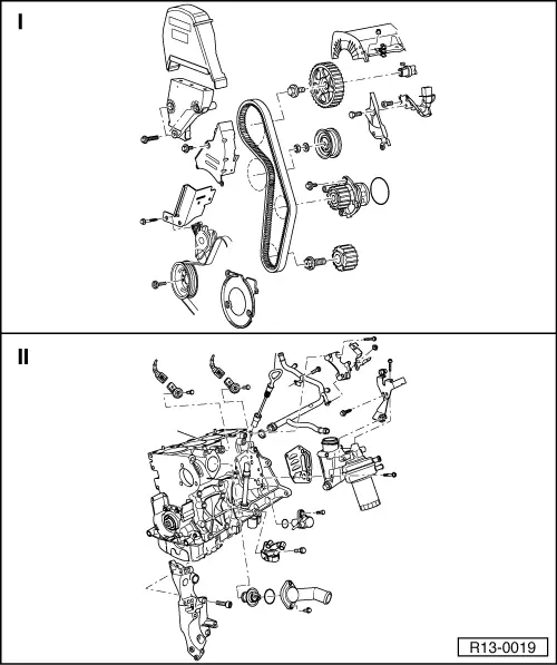
 Note
Note
|
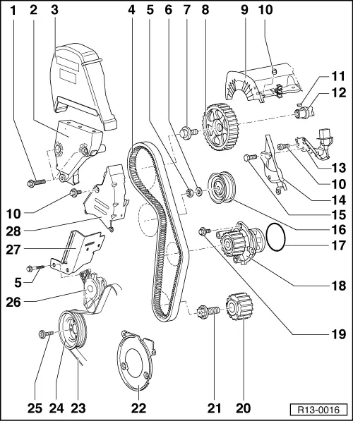
| 1 - | 50 Nm |
| 2 - | Engine support |
| 3 - | Mechanical distribution upper cover |
| 4 - | Timing belt |
| q | Mark the rotation direction before removing. |
| q | Check wear. |
| q | Do not bend. |
| q | Remove and install, adjust → Chapter. |
| 5 - | 20 Nm |
| 6 - | Washer |
| 7 - | 100 Nm |
| q | To remove and install, immobilise the camshaft gear with the Wrench -3415-. |
| 8 - | Camshaft gear |
| 9 - | Cylinder head cover |
| q | With cable guides. |
| 10 - | 10 Nm |
| 11 - | Key |
| q | Check the fitting. |
| 12 - | Camshaft |
| q | Check axial clearance → Fig. |
| q | Remove and install → Chapter. |
| q | Measure radial clearance with “Plastigage”: Wear limit: 0.1 mm. |
| q | Runout: max. 0.05 mm. |
| 13 - | Support |
| q | For Hall Sensor -G40-. |
| 14 - | Mechanical distribution rear cover |
| 15 - | 20 Nm |
| 16 - | Tensioning pulley |
| q | Check the timing belt semi-automatic tensioning pulley → Chapter. |
| 17 - | Sealing ring |
| q | Replace. |
| 18 - | Water pump |
| q | Check free movement. |
| q | In case of damage and leakage, cut and replace. |
| q | Remove and install → Chapter. |
| 19 - | 15 Nm |
| 20 - | Crankshaft gear |
| 21 - | 90 Nm 90° |
| q | Replace after each removal. |
| q | The thread and the head must be free from oil and grease. |
| q | To remove and install, use the Spanner -3415 -. |
| 22 - | Mechanical distribution lower cover |
| 23 - | Poly-V belt |
| q | Mark the rotation direction before removing. |
| q | Timing belt - remove and install → Chapter. |
| q | Poly-V belt travel → Chapter. |
| 24 - | Pulley/ vibration damper |
| q | The installation can only be made in one position. |
| q | Check position when installing the timing belt → Chapter. |
| 25 - | 40 Nm |
| 26 - | Tensioning element for Poly-V belts |
| q | For Poly-V belt. |
| q | Turn using a spanner to loosen the Poly-V belt → Chapter. |
| q | Timing belt - remove and install → Chapter. |
| 27 - | Support |
| 28 - | Mechanical distribution center cover |
|

| 1 - | 2 poles connector |
| q | For Knock sensor 1 -G61-. |
| q | Gilded contacts. |
| q | Do not invert. |
| 2 - | Knock sensor 1 -G61- |
| q | Gilded contacts. |
| 3 - | 20 Nm |
| q | Tightening torque influences Knock Sensor 1 -G61- operation. |
| 4 - | 2 poles connector |
| q | For Knock sensor 2 -G66-. |
| q | Gilded contacts. |
| q | Do not invert. |
| 5 - | Knock sensor 2 -G66- |
| q | Gilded contacts. |
| 6 - | Dipstick tube |
| 7 - | Oil dipstick |
| q | Oil level shall not exceed the Max. mark. ! |
| q | Marks → Fig. |
| 8 - | Cooling system tube |
| q | Cooling system hose connection diagram → Chapter. |
| 9 - | 25 Nm |
| 10 - | Support |
| q | For the Ignition transformer -N152 -. |
| 11 - | Support |
| 12 - | 10 Nm |
| 13 - | Support |
| 14 - | 10 Nm |
| 15 - | Sealing ring |
| q | Replace. |
| 16 - | Oil filter support |
| q | Remove and install → Chapter. |
| 17 - | 15 Nm 90° |
| q | Substituir após cada remoção. |
| 18 - | Gasket |
| q | Replace. |
| 19 - | Engine speed sensor -G28- |
| 20 - | Sealing ring |
| q | Replace when damaged. |
| 21 - | 40 Nm |
| 22 - | 15 Nm |
| 23 - | Connection nozzle |
| 24 - | Thermostat valve for the cooling system |
| q | Check: heat the cooling system thermostat valve in a double boiler. |
| q | Opening start with approx. 87° C. |
| q | Minimum opening travel 7 mm. |
| q | Remove and install → Chapter. |
| 25 - | 45 Nm |
| 26 - | Compact support |
| q | To the Generator (Alternator) -C-, air conditioning compressor and Poly-V belt tensioning element. |
| q | Compact support - remove and install in vehicles with air conditioning: → Aeration system ; Rep. Gr.87. |
| 27 - | Engine block |
| q | Sealing flanges and engine flywheel - remove and install → Chapter. |
| q | Crankshaft - remove and install → Chapter. |
| q | Pistons and connecting rods - assemble and disassemble → Chapter. |