| –
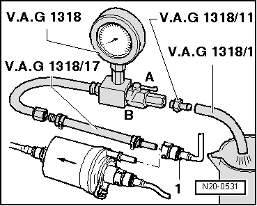
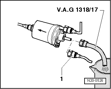
| Remove outlet hose from fuel filter position -1-. |

Note | To unfasten fuel lines, press the safety key. |
| –
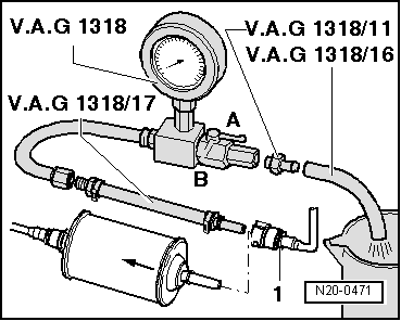
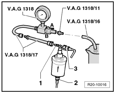
| Connect the Adapting set -VAG 1318/17- to position -1- of fuel filter outlet and to
the Pressure gauge -VAG 1318- . |
| –
| Install the Pressure gauge -VAG 1318- to the Adapter -VAG 1318/11- and
the Adapting set -VAG 1318/16-. |
| –
| The end of the Adapting set -VAG 1318/16- should be installed in a 3.0-liter (minimum) graduated container. |
| The procedures below are common for engines. |
| –
| Open the Pressure gauge -VAG 1318-valve. The valve points towards the direction of flow -A-. |
| –
| Activate the Remote control -VAG 1348/3A- and close the valve slowly until thePressure gauge -VAG 1318- reads a pressure of 3.0 bar (BAH engine)
and 4.2 bar (BPA/CCRA engines). Do not change the valve position any
more. |
| –
| Empty the graduated container. |
| –
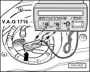
| The flow of the Fuel pump (pre-supply pump) -G6- depends on the Battery -A-voltage. Accordingly, connect a Multimeter -VAG 1715- to the Battery -A- using a Set of auxiliary measuring cables -VAG
1594C-. |
| –
| Activate the Remote control -VAG 1348/3A- for 30 seconds and measure voltage. |
| –
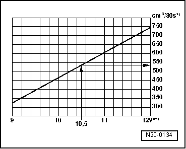
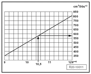
| Compare the Fuel pump (pre-supply pump) -G6- voltage and flow found with the theoretical value in
the graphic below: |
| If the flow found is the same or higher than the theoretical
value, the Fuel pump (pre-supply pump) -G6- is in top condition, as well as the fuel filter, the pipes and the
screen filter of the Fuel pump (pre-supply pump) -G6-. |
|
|
|
 WARNING