
Polo Mk4
|
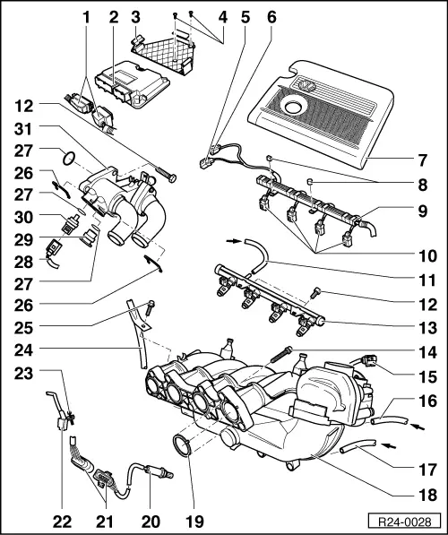
| 1 - | 80 pole connector |
| q | For Engine control unit -J623-. |
| q | Connect or disconnect the connector only with ignition switched off. |
| q | Unlock to remove. |
| 2 - | Engine control unit -J623- |
| q | For the injection system, lambda control, Magnetic valve I for activated charcoal reservoir -N80-, knock adjustment, speed limitation, ignition and self-diagnosis. |
| q | When replacing the Engine control unit -J623-, carry out adaptation → Chapter. |
| 3 - | Support |
| q | From the Engine control unit -J623-. |
| 4 - | 3 Nm |
| 5 - | Connector |
| q | Black, 4 poles. |
| q | From the Intake manifold pressure sensor -G71- with the intake air temperature sensor -G42-. |
| q | Gold plated connector contacts. |
| 6 - | Connector |
| q | Black, 3 poles. |
| q | From Engine speed sensor -G28-. |
| 7 - | Air filter set |
| q | Remove and install the air filter set → Chapter. |
| q | Disassemble and assemble → Chapter. |
| 8 - | Fastening clip |
| q | Observe model. |
| 9 - | Cable guide |
| q | Fastened to the fuel rail. |
| 10 - | Connector |
| q | Black, 2 poles. |
| q | From the Cylinder 1 injector -N30-,Cylinder 2 injector -N31-, Cylinder 3 injector -N32- and Cylinder 4 injector -N33-. |
| 11 - | Supply line |
| q | Black with white mark. |
| q | Fasten with spring braces. |
| q | Make sure it is well fastened. |
| q | From the fuel filter. |
| 12 - | 10 Nm |
| 13 - | Fuel rail with injectors |
| q | Remove and install → Chapter. |
| 14 - | 20 Nm |
| 15 - | Connector |
| q | Black, 6 poles. |
| q | For Throttle valve module -J338-. |
| q | Gold plated connector contacts. |
| 16 - | From the Magnetic valve I for activated charcoal filter -N80- |
| q | Fasten with spring braces. |
| 17 - | For brake servo |
| 18 - | Intake manifold |
| q | Remove and install → Chapter. |
| 19 - | Sealing ring |
| q | Replace. |
| q | Check installation position. |
| 20 - | Lambda probe -G39-, 50 Nm |
| q | Installation location: In the forward exhaust pipe. |
| q | Lubricate only the thread with High-temperature paste -G 052 112 A3-; do not reach probe body grooves. |
| q | Remove and install with the Set of sockets for Lambda probe -3337- for Lambda probe -G39-. |
| q | Power is supplied to heat the Lambda probe -G39- through the Fuel pump relay -J17-. |
| 21 - | Connector |
| q | Black, 4 poles. |
| q | For the Lambda probe -G39- before the catalytic converter and Lambda probe heating -Z19-. |
| q | Contacts 3 and 4 gold plated. |
| 22 - | Engine speed sensor -G28- |
| q | Installation location: On cylinder block, intake side. |
| 23 - | 5 Nm |
| 24 - | Guide tube |
| q | To the oil dipstick. |
| 25 - | 3 Nm |
| 26 - | Clip |
| q | Make sure it is well fastened. |
| 27 - | Washer |
| q | Replace. |
| 28 - | Connector |
| q | Black, 2 poles. |
| q | From Coolant temperature sensor -G62-. |
| q | Gold plated connector contacts. |
| 29 - | Plug |
| q | If necessary, depressurize the system before removal. |
| 30 - | Coolant temperature sensor -G62- |
| q | For Engine control unit -J623-. |
| q | If necessary, depressurize the system before removal. |
| 31 - | Thermostat housing |
|
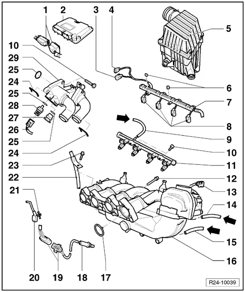
| 1 - | Connector |
| q | For Engine control unit -J623-. |
| q | Connect or disconnect the connector only with ignition switched off. |
| q | Unlock to disengage. |
| 2 - | Engine control unit -J623- |
| q | For the injection system, lambda control, magnetic valve I for the activated charcoal filter, knock adjustment, speed limitation, ignition and self-diagnosis. |
| q | When replacing the Engine control unit -J623-, adjust to Immobilizer control unit -J362- → Chapter. |
| 3 - | Connector |
| q | Black, 4 poles. |
| q | From the Intake manifold pressure sensor -G71- with the intake air temperature sensor -G42-. |
| q | Gold plated connector contacts. |
| 4 - | Connector |
| q | Black, 3 poles. |
| q | From Engine speed sensor -G28-. |
| 5 - | Air filter set |
| q | Disassemble and assemble → Chapter. |
| 6 - | Fastening clip |
| q | Observe model. |
| 7 - | Cable guide |
| q | Fastened to the fuel rail. |
| 8 - | Connector |
| q | Black, 2 poles. |
| q | From the Cylinder 1 injector -N30-,Cylinder 2 injector -N31-, Cylinder 3 injector -N32- and Cylinder 4 injector -N33-. |
| 9 - | Fuel supply lines |
| q | Black with white mark. |
| q | Fasten with spring braces. |
| q | Make sure it is well fastened. |
| q | From the fuel filter. |
| 10 - | 10 Nm |
| 11 - | Fuel rail with injectors |
| q | With Resistance for fuel pre-heating -Z66-, Resistance 2 for fuel pre-heating -Z108-, Resistance 3 for fuel pre-heating -Z109- and Resistance 4 for fuel pre-heating -Z110- only for vehicles equipped with E-Flex cold start system. |
| q | Remove and install → Chapter. |
| 12 - | 20 Nm |
| 13 - | Connector |
| q | Black, 6 poles. |
| q | For Throttle valve module -J338-. |
| q | Gold plated connector contacts. |
| 14 - | For Magnetic valve I for the activated charcoal filter -N80- |
| q | Fasten with spring braces. |
| 15 - | For brake servo |
| 16 - | Intake manifold |
| q | Remove and install → Chapter. |
| 17 - | Sealing ring |
| q | Replace. |
| q | Check installation position. |
| 18 - | Lambda probe behind catalytic converter -G130-, 50 Nm |
| q | Installation location: On the exhaust tube, front part, in 10/2010 with the OBD BR2. |
| q | Lubricate only the thread with High-temperature paste -G 052 112 A3-; ensure that the High-temperature paste -G 052 112 A3- does not reach the grooves on the body of Lambda probe after catalyst -G130-. |
| q | Remove and install with the Set of sockets for Lambda probe -3337-. |
| q | Power is supplied to heat the Lambda probe -G39- through the Fuel pump relay -J17-. |
| 19 - | Connector |
| q | Black, 4 poles. |
| q | To Lambda probe after the catalytic converter -G130- . |
| q | Contacts 3 and 4 gold plated. |
| 20 - | Engine speed sensor -G28- |
| q | Installation location: On cylinder block, intake side. |
| 21 - | 5 Nm |
| 22 - | Guide tube |
| q | To the oil dipstick. |
| 23 - | 3 Nm |
| 24 - | Clip |
| q | Make sure it is well fastened. |
| 25 - | Sealing ring |
| q | Replace. |
| 26 - | Connector |
| q | Black, 4 poles. |
| q | From Coolant temperature sensor -G62-. |
| q | Gold plated connector contacts. |
| 27 - | Plug |
| q | If necessary, depressurize the system before removal. |
| 28 - | Coolant temperature sensor -G62- |
| q | From the Engine control unit -J623-. |
| q | If necessary, depressurize the system before removal. |
| 29 - | Thermostat housing |