| –
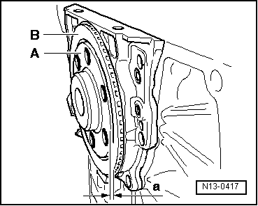
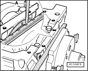
| Measure with razor caliper -A- the distance -a- between gauge rod and rotor. |
| If distance -a- is very small: |
| If distance is reached -a-: |
| –
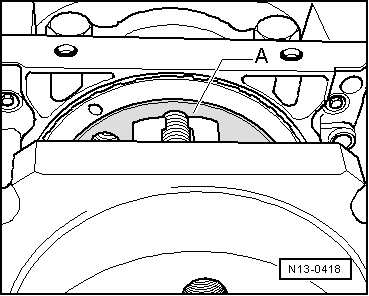
| Remove assembly device. |
| –
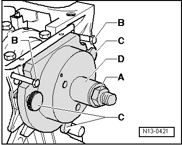
| Thread flange fastening bolts, alternating among them in cross. Tightening pair: 10 Nm |
|
|
|