
Polo Mk4
| Fuel container with accessory parts and fuel filter - remove and install |
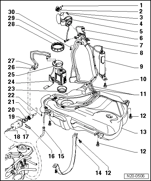
| 1 - | Fastener |
| 2 - | Container cover |
| 3 - | Sealing ring |
| q | Replace when damaged. |
| 4 - | Fastening bolt |
| 5 - | Fuel container cover |
| q | With rubber scoop |
| q | Remove and install → Body - External assembly jobs; Rep. Gr.55 |
| 6 - | Gravity valve |
| q | To remove, disconnect it from filling nozzle, upwards. |
| q | Check valve flow continuity. Valve upright: open. Valve tilted 45°: closed. |
| 7 - | Connect to ground |
| q | Ensure proper fastening. |
| 8 - | Ventilation tube |
| q | Ensure proper fastening. |
| 9 - | Activated charcoal filter |
| q | Installation location: on right rear wheel box. |
| 10 - | 10Nm |
| 11 - | Ventilation tube |
| q | fastened to activated charcoal filter. |
| q | Ensure proper fastening. |
| 12 - | 25Nm |
| 13 - | Fuel container |
| q | Remove using engine and transmission lifter Engine-/gearbox jack -V.A.G 1383/A-. |
| q | Remove and install → Chapter. |
| 14 - | Fastening belts |
| 15 - | Ventilation tube |
| q | Ensure proper fastening. |
| 16 - | Fastener |
| q | Ensure proper fastening. |
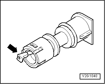
| 17 - | Fuel filter |
| q | Installation position: -arrow- indicates flow direction. |
| 18 - | Intake tubes |
| q | Black. |
| q | Ensure proper fastening. |
| q | Of fuel distributor. |
| 19 - | Sealing ring |
| q | Replace when damaged. |
| 20 - | Fastener |
| q | Replace. |
| 21 - | Fuel pressure regulator |
| 22 - | 5Nm |
| q | For fuel filter brace. |
| 23 - | Sealing ring |
| q | Replace when damaged. |
| q | To assemble, place it dry on fuel container opening |
| q | Lubricate with fuel only for flange installation. |
| 24 - | Fuel level indicator sensor |
| q | Remove and install → Chapter. |
| q | Adjust. → Electric diagrams, Fault location in the electric system and installation positions |
| 25 - | Fuel pump |
| q | Remove and install → Chapter. |
| q | Clean filter if dirty. |
| q | Check fuel pump → Chapter. |
| q | Observe fuel container installation position → Fig.. |
| 26 - | Return tubes |
| q | Blue |
| q | Fastened to the side of fuel container. |
| q | Ensure proper fastening. |
| 27 - | Intake tubes |
| q | Black. |
| q | Fastened to the side of fuel container. |
| q | Ensure proper fastening. |
| 28 - | Nut, 80Nm |
| q | Remove and install with wrench 3217. |
| 29 - | 10Nm |
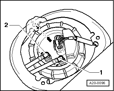
| 30 - | Ventilation valve |
| q | Check → Fig.. |
| q | To remove, slightly press lock inwards and remove valve. |
 Note
Note
|
|