volkswagen Workshop Repair Guides

Volkswagen Workshop Service and Repair Manuals

Gear components > < Electric and electronic components and their location
Components in the vehicle
   
Components in the vehicle
1 - Automatic gearbox control unit -J217-
q   Location
2 - Engine control unit
q   For further information → Fig.
3 - Potentiometer of the butterfly -G69-, Transmitter of accelerator position -G79-
q   For further information → Fig.
4 - Kick-down switch
q   The signal is originated in the "electronic accelerator".
5 - Gearbox
q   Electric/electronic components of the gearbox → Chapter
6 - Brakelight switch -F-
q   Location → Fig.
7 - Relay for blocking the start -J207-
q   Location → Fig.
8 - Relay for reversing light -J219-
q   Location → Fig.
9 - Diagnosis connection
10 - Electromagnet for blocking the selector lever -N110-
q   Disassemble and assemble → Chapter

   
Indicator of selected range -Y5-
Location: the indicator is located in the instrument panel.
If the emergency program is activated and the control unit is working, all segments of the indicator of selected range located in the instrument panel will light up.
If the emergency program is activated but the control unit does not work, no position in the selector lever will light up.
The indicator is controlled by the diagnosis interface for the data bus.
  N01-0135
Location of the automatic gearbox control unit -J217-
The control unit (arrow) is located in the water tank.
–  After assembly. Start the basic adjustment.
To do so:
t  Connect the equipment VAS 5051 and switch until "Select functions/components" appears
t  Press "Power-drive (Rep. Group 01; 10...26; 28...39)".
t  Then, "4-speed automatic gearbox 001".
t  Press "01 - Self-diagnosis".
t  Press "Functions".
t  Press "J217 - Perform basic adjustment".
  N37-0988
Fig.1-Engine control unit
Location: the control unit is located in the water tank.
–  After assembly. Start the basic adjustment.
To do so:
t  Connect the equipment VAS 5051 and switch until "Select functions/components" appears
t  Press "Power-drive (Rep. Group 01; 10...26; 28...39)".
t  Then, "4-speed automatic gearbox 001".
t  Press "01 - Self-diagnosis".
t  Press "Functions".
t  Press "J217 - Perform basic adjustment".
  N01-0138
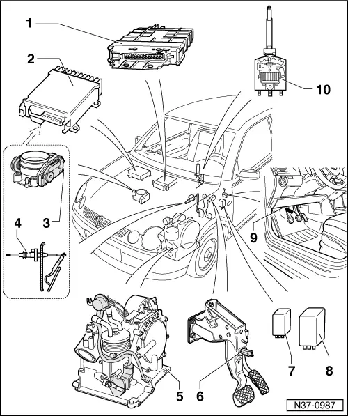
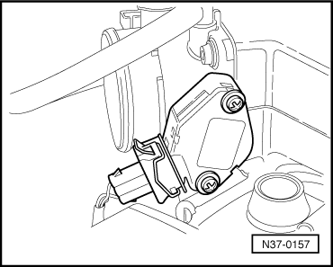
Fig.2-Potentiometer of butterfly -G69- or transmitter of accelerator position -G79-
Location:
The potentiometer is part of the butterfly command unit -J338-. It is located at the chute of the butterfly command unit (engine).
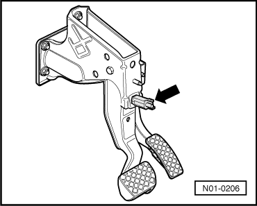
The transmitter of accelerator position -G79-, component of the electronic adjustment of engine power (electronic accelerator), is located in the pedals.
–  Potentiometer of butterfly: verify and adjust, or disassemble and assemble → Rep. Gr.24
–  After assembly. Start the basic adjustment.
To do so:
t  Connect the equipment VAS 5051 and switch until "Select functions/components" appears
t  Press "Power-drive (Rep. Group 01; 10...26; 28...39)".
t  Then, "4-speed automatic gearbox 001".
t  Press "01 - Self-diagnosis".
t  Press "Functions".
t  Press "J217 - Perform basic adjustment".
  N37-0157
Fig.3-Relay for blocking the start -J207- and relay for reversing light -J219-
Location: the relay -J207- is located in the relay holder, behind the fuse holder below the left side of the instrument panel → Current circuit schemes.
The relay -J219- is located in the control unit of the multifunction centre -J501-.
  N37-0357
Fig.4-Brakelight switch -F-
Location: the brakelight switch (arrow) is located in the pedals.
–  Disassembly, assembly and adjustment of the brakelight switch → Rep. Gr.46
  N01-0206

Gear components > < Electric and electronic components and their location