volkswagen Workshop Repair Guides

Volkswagen Workshop Service and Repair Manuals

Assembly > < Assembly
Selector lever: disassemble and assemble
   
–  In vehicles with code radio equipment, take the code into account; if necessary, consult it.
–  Disconnect the earth strap from the battery.
–  Turn the sleeve -5- located in the selector lever knob 90°.
–  Remove the selector lever knob by pulling it upwards.
–  Disassemble the central console, at the back. → Rep. Gr.68
–  Uncouple the end of the blocking cable located in the selector lever case from the blocking connecting rod → Chapter
–  Separate the cable clamp -1- from the selector lever case.
Avoid damaging the cables!
–  Carefully remove from the selector lever case the support to the connector -2- making a lever with a screwdriver.
  N37-0998
–  Unplug the connector -3- for the selector lever blocking electromagnet and the -4- for the lever position indicator.
–  Disengage, with your hands, the lips -6- (4 units) from the selector lever case cover and remove the cover.
–  Detach the frame carefully, making a lever, by the four edges -7- and disassemble it. Avoid damages to the contact spring of the selector lever position indicator!
–  Unscrew the elements for frontal fastening (2 nuts) of the transmission activation mechanism.
  N37-0998
–  Disassemble the adjusting washer from the idler -1-.
–  The adjusting washer from the selector lever cable in the the transmission idler must always be replaced after being disassembled.
–  Remove the selector lever cable from the selector axle connecting rod -2-.
–  Raise the vehicle. Separate the exhaust gas system. → Rep. Gr.26
–  Disassemble the tunnel's heat insulation plate.
–  Remove the cover from the selector lever case.
  N37-0991
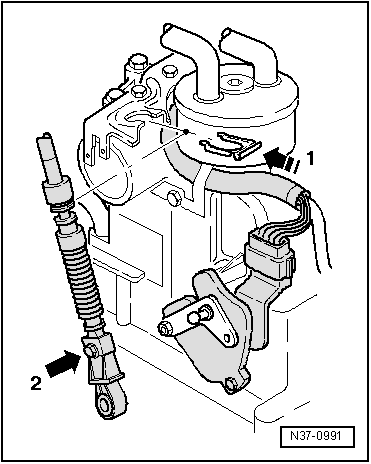
–  Separate the cable --3- from the selector lever -2- making a lever with a screwdriver
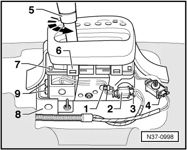
–  Extract, pulling downwards, the adjusting washer -1- that fastens the selector lever cable to the selector lever case.
–  Remove the selector lever cable from the case pulling carefully.
–  Remove the rear screws that fasten the selector lever case
–  Support the transmission activation mechanism from below.
–  Remove the screws (2 units) that fasten the electromagnet.
–  With the selector lever always in the position "1", remove the electromagnet from the selector lever case along with the retaining pin and the spring, simultaneously moving the lever slightly to one side and to another, if necessary
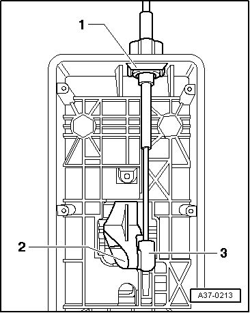
–  Release the nut to the selector lever supporting pin by immobilizing only the hexagonal part of the pin (the pin must not turn).
–  Carefully remove the supporting pin using a mandrel
–  Remove the selector lever.
  A37-0213

Assembly > < Assembly