
Polo Mk4
| Pinion shaft - disassemble and assemble |

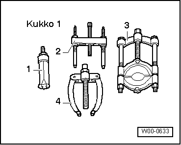
| Special tools and workshop equipment required |
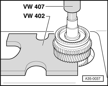
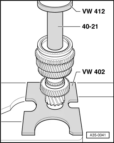
| t | Plate -VW 402- |
| t | Pressure pin -VW 407- |
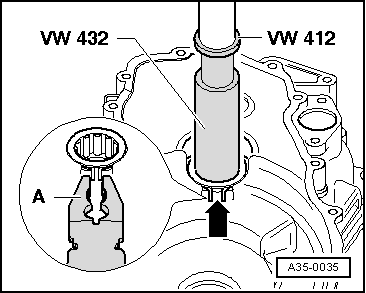
| t | Pressure disc -VW 412- |
| t | Pressure tube -VW 415A- |
| t | Pressure base -VW 432- |
| t | Supporting tube -40-21- |
|
 Note
Note
|
|
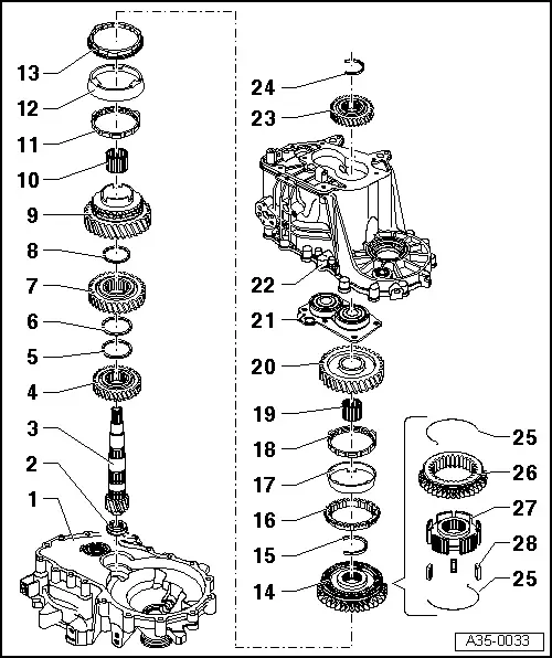
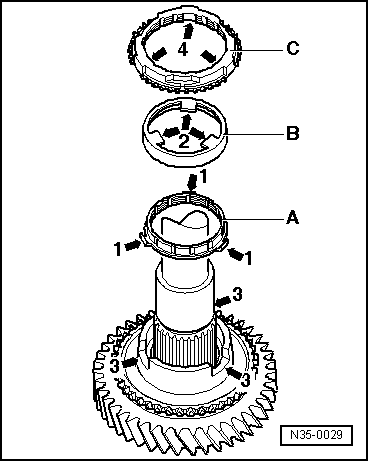
| 1 - | Clutch case |
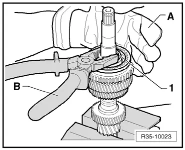
| 2 - | Tapered roller bearing |
| q | With circlip |
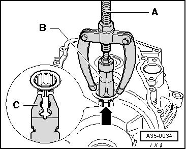
| q | Removal → Fig. |
| q | Installation → Fig. |
| q | Installation position: the circlip shall face the pinion shaft |
| 3 - | Pinion shaft |
| q | If replacement is required, the differential master gear must also be replaced → Item. |
| q | If there is an inside ring as tapered roller bearing housing, this should not be removed from the pinion shaft. |
| q | If scratches or damages are detected on the bearing housing or inside ring, replace the pinion shaft and the tapered roller bearing as a set. |
| 4 - | 4th gear wheel |
| q | Installation position: the hub shall face the 3rd gear → Fig. |
| 5 - | Circlip |
| 6 - | Circlip |
| 7 - | 3rd gear wheel |
| q | Installation position: the hub shall face the 3rd gear → Fig. |
| 8 - | Circlip |
| 9 - | 2nd gear wheel |
| 10 - | Needle bearing |
| q | For 2nd gear |
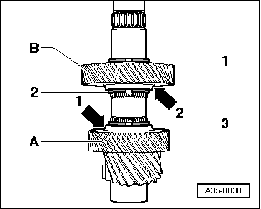
| 11 - | Inside ring for 3rd gear |
| q | Wear check → Fig. |
| q | Installation position → Fig. |
| 12 - | Outside ring for 2nd gear |
| q | Install on inside ring → Item |
| q | Change in case of scratches or wear signs |
| q | Installation position → Fig. |
| 13 - | Synchroniser ring for 2nd gear |
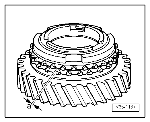
| q | Wear check → Fig. |
| q | Installation position → Fig. |
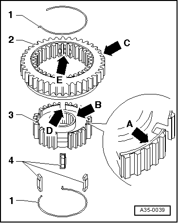
| 14 - | Engaging sleeve with 1st and 2nd gear synchroniser |
| q | Remove with 2nd gear wheel after removing the circlip → Fig. |
| q | Disassemble and assemble the engaging sleeve/synchroniser ring → Fig. |
| q | Installation → Fig. |
| 15 - | Circlip |
| q | Removal → Fig.. |
| q | Installation → Fig. |
| 16 - | Synchroniser ring for 1st gear |
| q | Wear check → Fig. |
| q | Install in order that the notches fit in the engaging sleeve limiters → Item |
| 17 - | Outside ring for 1st gear |
| q | Install on synchroniser ring → Item |
| q | Installation position → Fig. |
| q | Change in case of scratches or wear signs |
| 18 - | Inside ring for 1st gear |
| q | Wear check → Fig. |
| q | Check the flanges for wear signs |
| q | Installation position → Fig. |
| 19 - | Needle bearing |
| q | For 1st gear |
| 20 - | 1st gear wheel |
| q | Installation position → Fig. |
| 21 - | Bearing support with ball bearing |
| q | Change bearing support with ball bearing |
| q | Clean the threaded holes of the bearing support (e.g. Tap M6) |
| q | Removal → Fig.. |
| q | Installation → Fig. |
| 22 - | Transmission case |
| 23 - | 5th gear wheel |
| q | Installation position: the hub shall face the transmission case side → Fig. |
| 24 - | Circlip |
| q | Always replace |
| q | Determine thickness → Anchor |
| 25 - | Spring |
| q | Installation position → Fig. |
| 26 - | Engaging sleeve |
| 27 - | Synchroniser |
| 28 - | Retainers |
| q | 3 units |
|
|
|
|
 WARNING
|
|
|
|
|
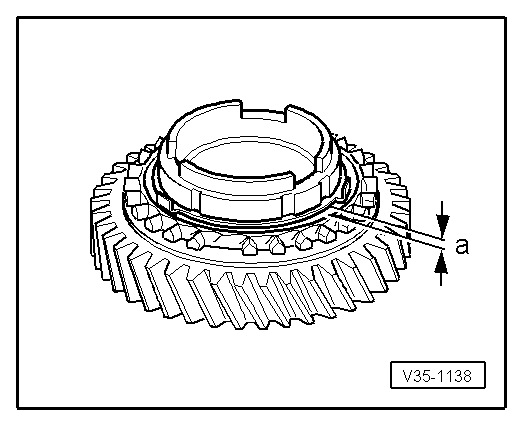
|
| Distance -a- | New part | Wear limit |
| 1st and 2nd gears | 0,75 ... 1.25 mm | 0.3 mm |
|
|
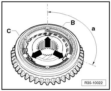
| Distance -a- | New part | Wear limit |
| 1st and 2nd gear | 1,2 ... 1.8 mm | 0.5 mm |
|
|
|
|
Note
|
|
|
|
|
|
|
|
|
|
|
|