
Polo Mk5
|
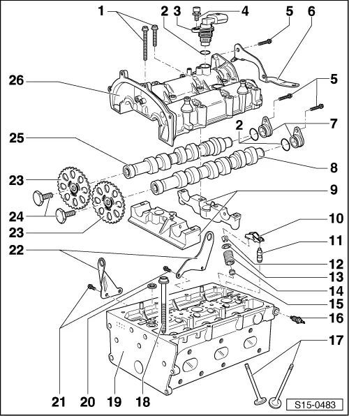
| 1 - | 10 Nm + turn 90° further |
| q | Renew. |
| q | Tighten from inside outwards. |
| 2 - | O-ring |
| q | Renew if damaged. |
| 3 - | Hall sender -G40- |
| 4 - | 8 Nm |
| 5 - | 10 Nm |
| 6 - | Bracket |
| q | For wiring harness. |
| 7 - | Cap |
| 8 - | Exhaust camshaft |
| 9 - | Camshaft bearing caps |
| 10 - | Roller rocker finger |
| q | Check roller bearing for ease of movement. |
| q | Oil contact surface. |
| q | When installing, secure to supporting element using securing clip. |
| 11 - | Support element |
| q | Do not interchange. |
| q | With hydraulic valve clearance compensation. |
| q | Before installing, check camshaft axial clearance → Chapter. |
| q | Oil contact surface. |
| 12 - | Cotters |
| 13 - | Valve spring plate |
| 14 - | Valve spring |
| q | With cylinder head removed, use hold down tool for valve springs -3362-. |
| q | With cylinder head installed → Chapter. |
| 15 - | Valve stem seal |
| q | Renewing → Chapter. |
| 16 - | 0.3…0.7 bar oil pressure switch -F1-, 25 Nm |
| q | Check → Chapter. |
| 17 - | Valves |
| q | Do not rework, only lapping-in is permitted. |
| q | Valve dimensions → Fig.. |
| 18 - | Cylinder head bolt |
| q | Renew. |
| q | Follow installation instructions and sequence when loosening and tightening → Chapter. |
| 19 - | Cylinder head |
| Removing and installing → Chapter. |
| q | Reworking valve seat → Chapter. |
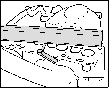
| q | Checking cylinder head for distortion → Fig. |
| q | Reworking sealing surface → Fig.. |
| 20 - | Seal |
| q | Clean strainer if soiled. |
| 21 - | 20 Nm |
| 22 - | Lifting eye |
| 23 - | Chain sprocket |
| q | For camshaft. |
| q | Lock chain sprocket using counterhold -T10172-. |
| 24 - | 50 Nm + turn 90° further |
| q | Renew. |
| q | Lock chain sprockets using counterhold -T10172-. |
| 25 - | Inlet camshaft |
| 26 - | Camshaft housing |
 Caution
|
| q | Removing and installing → Chapter. |
| q | Remove sealant residue. |
| q | Coat with D 154 103 A1 before fitting. |
| q | When installing, fit vertically from above onto studs and dowel pins. |
|
|