
Polo Mk5
|
 Caution
 Note
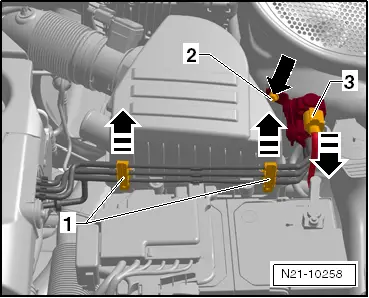
Note| t | Blue = vacuum control line for exhaust gas recirculation. |
| t | Grey = breather line from air filter housing. |
| t | Green = vacuum control line for turbocharger. |
| t | Red = vacuum line from vacuum pump. |

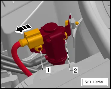
| 1 - | Vacuum unit |
| q | For changeover for exhaust gas recirculation cooler. |
| 2 - | Non-return valve |
| 3 - | Exhaust gas recirculation cooler changeover valve -N345- |
| q | Checking changeover → Chapter. |
| 4 - | Cylinder head cover |
| q | With integrated vacuum reservoir |
| 5 - | Vacuum unit |
| q | On turbocharger. |
| q | With position sender for charge pressure positioner -G581-. |
| 6 - | To intake hose |
| 7 - | Vacuum line |
| q | To brake servo. |
| 8 - | Vacuum pump |
| 9 - | Charge pressure control solenoid valve -N75- |
|
|
|
|