volkswagen Workshop Repair Guides

Volkswagen Workshop Service and Repair Manuals

Checking compression > < Removing and installing cylinder head
Removing and installing camshaft housing
  Note
t  The camshafts cannot be removed.
t  If repair is required, the camshaft housing and the camshafts need to be renewed as a complete unit.
   
Special tools and workshop equipment required
t  Support bracket -10 - 222 A-
t  Engine support basic set -T40091-
t  Assembly tool -T10476-
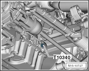
t  Locking pin -T10340-
t  Camshaft clamp -T10477-
t  Torque wrench -V.A.G 1332-
t  Adapter -10-222 A/31-2- (not illustrated)
t  Support -10-222 A/31-3- (not illustrated)
t  Adapter -10-222 A/31-5- (not illustrated)
t  Square tube -T40091/1- (not illustrated)
t  Connector -T40091/3- (not illustrated)
t  Shackle -10-222 A/12- (not illustrated)
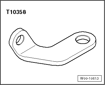
t  Bracket -T10358-

Removing
–  First check whether a coded radio is fitted. If so, obtain anti-theft coding.
–  With ignition switched off, disconnect battery earth strap.
–  Remove air filter housing → Chapter.
  W00-10513
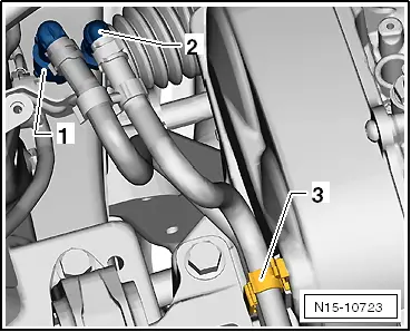
–  Unlock and disconnect fuel supply line -1- and breather line -2-. → Fuel supply system - Petrol engines; Rep. gr.20.
–  Open line guide -3- and detach hoses.
–  Seal lines so that fuel system is not contaminated by dirt.
–  Detach clips -arrows-.
  N15-10723
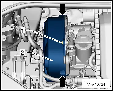
–  Unscrew securing bolt -1- and remove cover -2-.
–  Unscrew securing bolts -arrows-.
  N15-10724
–  Unclip line guide from cover.
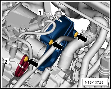
–  Remove cover -1- and cover -2-.
  N15-10725
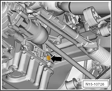
–  Unscrew plug -arrow- from crankcase.
–  Lower lifting platform completely.
  Note
t  The lifting platform must be lowered completely in order to allow for screwing the locking pin -T10340- into the crankcase.
t  When the vehicle is raised, the hole is hidden behind the drive shaft.
  N15-10726
–  Screw locking pin -T10340- into crankcase from above as far as it will go.
  Caution
If locking pin -T10340- cannot be screwed in as far as stop, this indicates that crankshaft is not in the correct position!
In this case, proceed as follows.
–  Unscrew locking pin.
–  Turn crankshaft 90° in direction of rotation of engine.
–  Screw locking pin -T10340- into crankcase as far as it will go.
–  Tighten locking pin -T10340- to 30 Nm.
–  Turn crankshaft in direction of rotation of engine as far as the stop.
Locking pin -T10340- locks crankshaft in direction of engine rotation.
  N15-10727
–  Grooves -1- of inlet camshaft -3- are positioned right above horizontal camshaft centre line -2-.
–  Grooves -1- of exhaust camshaft are positioned right above horizontal camshaft centre line -2-.
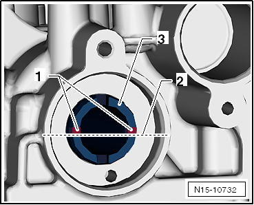
  N15-10732
–  Recesses of gear -3- in area of grooves are slightly more oriented above horizontal camshaft centre line.
  Caution
The camshaft clamp -T10477- must slide into position easily.
The camshaft clamp must not be positioned using any kind of hammer.
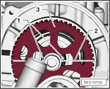
  N15-10730
–  Insert camshaft clamp -T10477- to stop into camshafts and tighten bolt -arrow- by hand.
–  Drain coolant → Chapter.
–  Remove coolant pump → Chapter.
  Note
The coolant pump toothed belt pulley is not being removed from the camshaft.
–  Remove throttle valve module -J338- → Chapter.
  N15-10733
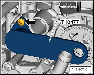
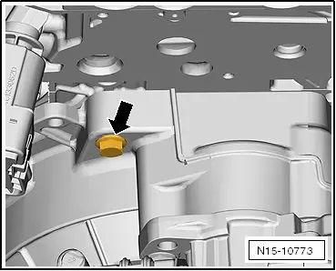
–  Remove securing bolt -arrow- for gearbox.
–  Connect bracket -T10358- to gearbox using securing bolt.
–  Removing and installing poly V-belt → Chapter
–  Remove windscreen wiper arms → Electrical system; Rep. gr.92.
–  Remove plenum chamber cover → General body repairs, exterior; Rep. gr.50.
  N15-10773
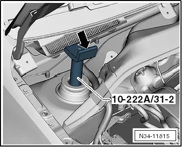
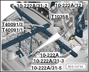
–  Fit adapter -10-222A/31-2- onto suspension struts.
–  Angle pieces of adapter -arrow- point towards engine compartment.
  N34-11815
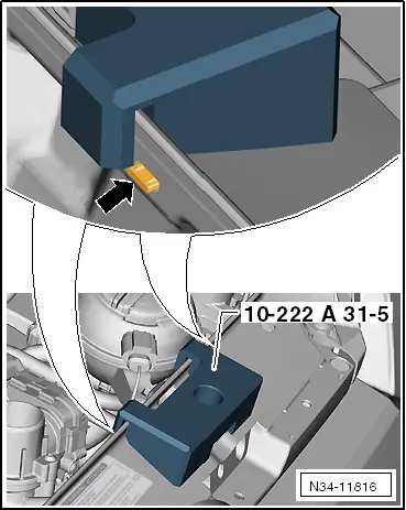
–  Position support -10-222A/31-5- above bonnet catch.
–  Correct position is between 2 lugs -arrow-.
–  Fit support bracket -10 - 222 A- and engine support basic set -T40091- with adapters as shown.
  N34-11816
–  Bolt shackle -10-222 A/12- to bracket -T10358-.
–  Attach hook with spindle to shackle and slightly release load from assembly mounting by turning spindle.
–  Unscrew earth wire -1-.
  N15-10799
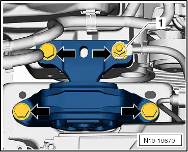
Unscrew securing bolts -arrows- and remove assembly mounting on engine side.
  N10-10670
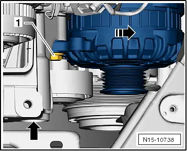
–  Unscrew securing bolts -1- and swivel alternator in -direction of arrow-.
–  Lift motor up sufficiently by turning spindle in order to allow for unscrewing securing bolt of engine mounting.
  N15-10738
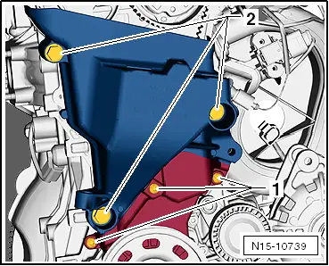
–  Unscrew securing bolts -2- of engine mounting and 3 bolts -1- of lower toothed belt guard.
–  Lift out engine mounting upwards.
  Caution
When loosening and tightening the securing bolts, the camshaft sprockets must in any case be secured with the counterhold -T10172-.
The camshaft clamp -T10477- may not be subjected to load when tightening the camshaft sprockets in order to avoid damage to the tool or to the camshafts.
  N15-10739
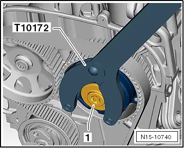
–  Secure camshaft adjuster with counterhold -T10172- and unscrew plug -1-.
  Note
When adjusting the valve timing, both camshaft sprockets must be loose.
–  Secure camshaft adjuster and camshaft sprocket with counterhold -T10172-.
  N15-10740
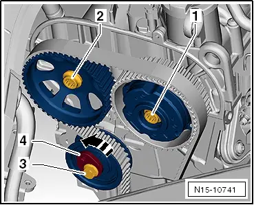
–  Loosen securing bolts -1- and -2-.
–  Loosen securing bolt -3- of belt tensioner and release tension of belt tensioner by turning the eccentric -4- (hexagon socket insert) in -direction of arrow-.
–  Push toothed belt from camshaft sprockets.
  N15-10741
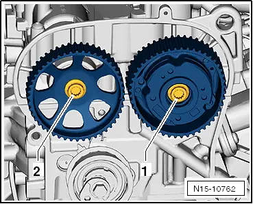
–  Unscrew securing bolts -1- and -2- and remove camshaft sprockets.
  Note
The securing bolts -1- and -2- must be renewed.
  N15-10762
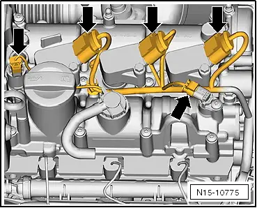
–  Disconnect connector -arrows- and unclip line guide from camshaft housing.
  N15-10775
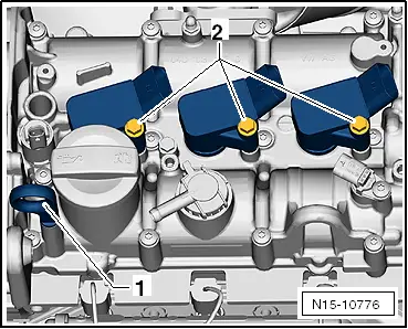
–  Pull out oil dipstick -1- and unscrew securing bolts -2- of ignition coils with output stages.
–  Pull off ignition coils with output stages from spark plugs.
  N15-10776
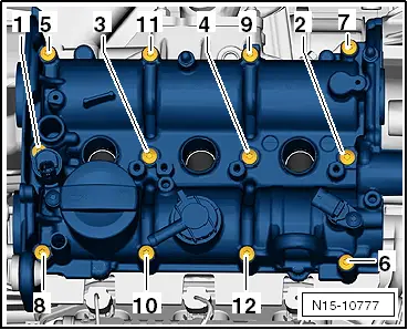
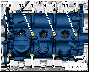
–  Loosen securing bolts -1- through -12- of camshaft housing in sequence given and then remove completely.
–  Lift off camshaft housing vertically from cylinder head.
–  Remove gasket.
–  Clean sealing surfaces. They must be free of oil and grease.
Installing
Prerequisite
l  The pistons must not be positioned at TDC.
  Note
If a piston is at TDC, the valves could strike the piston when the camshafts turn.
  N15-10777
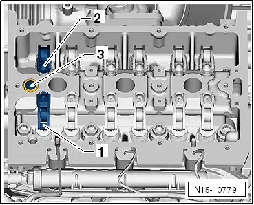
–  Ensure that all roller rocker fingers are correctly clipped into the valve stem ends -1- and into their respective support elements -2-.
–  Renew seal and oil strainer -3-.
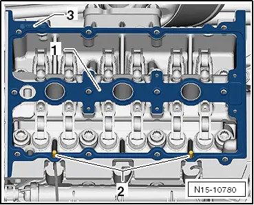
–  Fit new gasket -1- onto dowel pins -2-.
  N15-10779
Part number -3- of gasket must be readable from above.
  Caution
When positioning the camshaft housing onto the cylinder head, it must be prevented from canting.
This prevents the roller rocker fingers from slipping out of the valve stem ends and the support elements.
  N15-10780
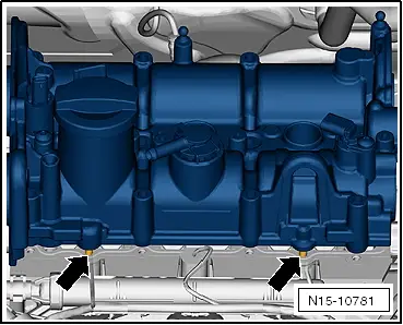
–  Carefully fit camshaft housing vertically from above onto dowel pins -arrows-.
Bear in mind different bolt lengths.
  N15-10781
–  Tighten new securing bolts -1- through -12- of camshaft housing in sequence given to 10 Nm + 180°.
–  Adjusting valve timing → Chapter.
Specified torques for assembly mounting: → Chapter
Specified torques for gearbox: → Rep. gr.34
Install coolant pump → Chapter.
–  Install throttle valve module -J338- → Chapter.
–  Replenish coolant → Chapter.
Further assembly is basically the reverse of the dismantling sequence.
  N15-10778

Checking compression > < Removing and installing cylinder head