volkswagen Workshop Repair Guides

Volkswagen Up! Auto Repair Manuals and Service Guides

Removing and installing valve stem seals > < Belt pulley end
Gearbox side
   
Gearbox side
Special tools and workshop equipment required
t  Locking pin -T10340-
t  Camshaft clamp -T10477-
t  Puller hooks -T20143/1-
t  Assembly tool -T10479-
t  Torque wrench -V.A.G 1331-
t  Torque wrench -V.A.G 1410-

Removing
–  Drain coolant → Chapter.
–  Pull hose -1- off air filter housing.
   
–  Pull air filter housing upwards off studs at positions -2- and -3-.
–  Push air filter housing and intake connecting pipe in -direction of arrow- out of mounting -4-.
–  Remove air filter housing from engine compartment.
  N15-10801
–  Unlock and disconnect fuel supply line -1- and breather line -2-. → Fuel supply system - Petrol engines; Rep. gr.20.
–  Open line guide -3- and detach hoses.
–  Seal lines so that fuel system is not contaminated by dirt.
–  Detach clips -arrows-.
  N15-10723
–  Unscrew securing bolt -1- and remove cover -2-.
–  Unscrew securing bolts -arrows-.
  N15-10724
–  Unclip line guide from cover.
–  Remove cover -1- and cover -2-.
  N15-10725
–  Disconnect all coolant hoses -1- from coolant pump.
  N10-10657
–  Unscrew plug -arrow- from crankcase.
–  Lower lifting platform completely.
  Note
t  The lifting platform must be lowered completely in order to allow for screwing the locking pin -T10340- into the crankcase.
t  The locking pin is installed from above.
t  When the vehicle is raised, the hole is hidden behind the drive shaft.
  N15-10726
–  Screw locking pin -T10340- into crankcase from above as far as it will go.
  Caution
If locking pin -T10340- cannot be screwed in as far as stop, this indicates that crankshaft is not in the correct position!
In this case, proceed as follows.
–  Unscrew locking pin.
–  Turn crankshaft 90° in direction of rotation of engine.
–  Screw locking pin -T10340- into crankcase as far as it will go.
–  Tighten locking pin -T10340- to 30 Nm.
–  Turn crankshaft in direction of rotation of engine as far as the stop.
Locking pin -T10340- locks crankshaft in direction of engine rotation.
  N15-10727
Marked gap -1- of camshaft adjuster -3- is aligned with lug -2- of camshaft housing.
  N15-10731
Marked tooth -1- of exhaust camshaft sprocket -3- is aligned with lug -2- of camshaft housing.
  N15-10729
–  Grooves -1- of inlet camshaft -3- are positioned right above horizontal camshaft centre line -2-.
–  Grooves -1- of exhaust camshaft are positioned right above horizontal camshaft centre line -2-.
  N15-10732
–  Recesses of gear -3- in area of grooves are slightly more oriented above horizontal camshaft centre line.
  Caution
The camshaft clamp -T10477- must slide into position easily.
The camshaft clamp must not be positioned using any kind of hammer.
  N15-10730
–  Insert camshaft clamp -T10477- to stop into camshafts and tighten bolt -arrow- by hand.
  N15-10733
–  Mark position of coolant pump gear -1- with a marker -2- at lug -3-.
  Note
t  The marking will be used for installing the gear at the correct position at a later point.
t  Otherwise the camshaft clamp -T10477- cannot be inserted.
–  Remove retaining ring -arrow- of gear selector cable.
  N15-10756
–  Remove gear selector cable -1- from selector lever and lay to side.
  N15-10761
–  Unscrew securing bolts -1- through -5- of coolant pump in sequence given.
–  Remove coolant pump.
  N15-10757
–  Unscrew bolt -arrow- and remove camshaft clamp -T10477- from camshafts.
–  Remove toothed belt -1- from coolant pump toothed belt pulley.
  N15-10758
–  Secure toothed belt pulley -2- with counterhold -T10172- and unscrew securing bolt -1-.
–  Remove toothed belt pulley.
  N15-10759
–  Carefully fit extractor hook -T20143/1- between camshaft and seal -1-.
–  Lever out seal -1-.
Installing
  N15-10747
–  Put together assembly sleeves -T10479/2- and -T10479/3-.
–  Fit new seal in -direction of arrow- onto assembly sleeve -T10479/2-.
  N15-10748
–  Disconnect assembly sleeves -T10479/2- and -T10479/3- in -direction of arrow-.
  N15-10749
–  Fit assembly sleeve -T10479/2- with seal -1- on camshaft.
–  Fit thrust piece -T1047971- onto assembly sleeve and draw it in to stop with securing bolt -2-.
–  Mount toothed belt pulley -2- on camshaft with securing bolt -1-.
  N15-10750
Marking on toothed belt pulley must be aligned with lug.
–  Secure toothed belt pulley -2- with counterhold -T10172-.
–  Tighten securing bolt -1- to 20 Nm.
–  Moisten coolant pump seal with coolant.
–  Fit toothed belt centrally onto camshaft sprocket and coolant pump toothed belt pulley.
–  Mount coolant pump on cylinder head with securing bolts.
  Caution
Always adhere to the sequence of work steps given below when installing the coolant pump.
This ensures that the toothed belt is correctly tensioned.
The following work steps should be carried out with the aid of a 2nd mechanic.
–  First tighten securing bolts in sequence -1- to -5- to 10 Nm.
  N15-10759
–  Then, loosen all bolts by 180°.
  N15-10760
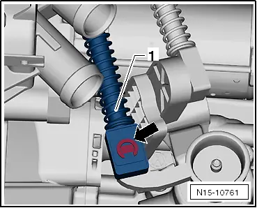
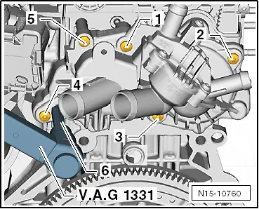
–  Using hexagon on coolant pump, preload coolant pump to 35 mm using 10 mm hexagon socket -6-, universal joint, extension and torque wrench -V.A.G 1331-.
–  Keep torque wrench -V.A.G 1331- pushed to that torque.
–  Support extension and universal joint with other hand.
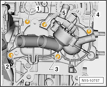
–  Tighten securing bolts -1- through -5- clockwise in sequence given to 12 Nm.
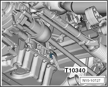
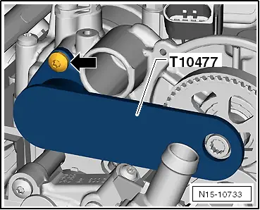
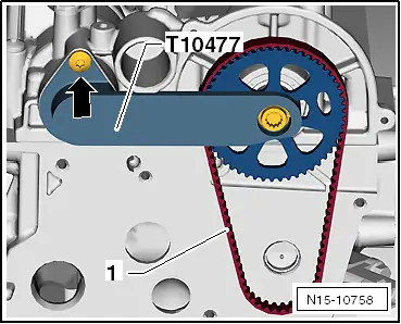
  Caution
After completing work, it is essential to ensure that the locking pin -T10340- and the camshaft clamp -T10477- have been removed.
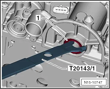
Specified torque for crankcase plug: 30 Nm.
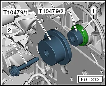
Further assembly is basically the reverse of the dismantling sequence.
–  Install selector mechanism to gearbox: → Rep. gr.34.
–  Replenish coolant → Chapter.
–  Install air filter housing → Chapter.
  N15-10760

Removing and installing valve stem seals > < Belt pulley end