| Removing and installing onboard supply control unit |
| The onboard supply control unit -J519- is fastened to the rear of the relay carrier in the driver side footwell and performs the following functions in the vehicle. |
| t
| Electrical load management |
| t
| Transfer of dimming information on the CAN bus |
| t
| Windscreen wiper speeds I, II and intermittent wipe |
| t
| Reading in of sender unit button for emergency braking function |
| t
| Operation of hazard warning flasher, turning signals, emergency braking warning flasher |
| t
| Terminal detection, terminal 15; S-contact |
| t
| Rear lid release without central locking |
| t
| Terminal 30, interior light |
| The following functions can be adapted → Chapter: |
| t
| Adapting remote control key |
| t
| Checking remote control unit key |
| t
| Deactivating factory mode |

Note | t
| If the onboard supply control unit -J519- is to be renewed, the procedure for „replacing onboard supply control unit“ → Chapter must always be carried out for reading the codes stored in the control unit. |
| t
| The following illustrations show removal on a LHD model. Removal and installation of onboard supply control unit on an RHD vehicle are performed using the corresponding mirror-image procedure. |
| Replacement of onboard supply control unit: |
| –
| First of all, carry out the work involved in „replacing the onboard supply control unit“ → Chapter. |
| –
| Switch off ignition and all electrical loads, and pull out ignition key. |
Note | For reasons of space, the fuse holder has to be removed from the relay carrier but can remain connected. |
| –
| Remove fuse holder from relay carrier → Chapter. |
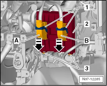
Note | The following illustration shows the installed onboard supply control unit on the rear of the relay carrier. |
|
|
|