
Vanagon F4-1970cc 2.0L (1982)
Hall Effect Sensor: Testing and Inspection
Hall generator, checking
Test conditions:
disconnect both wire plugs from idle stabilizer and connect them together
Hall control unit OK
ignition coil OK
wiring between Hall control unit and ignition coil OK
connector pins and sockets on Hall-generator
CAUTION: When working on vehicles with Hall ignition system, observe following precautions to prevent injury or damage to ignition system:
-
do not touch or remove high tension wire when running or cranking engine
-
disconnect ignition wires only when ignition is switched oft
-
test instruments should be connected! disconnected only when ignition is switched off
-
do not connect any condenser to terminal 1
-
do not tow cars without disconnecting plugs on ignition control unit
-
do not crank engine unit high tension wire of distributor cap (terminal 4) is connected to ground with jumper wire (example: compression check,
etc.)
-
do not leave battery connected when electric welding on car
-
do not substitute rotor of ignition distributor with one of different type
-
when installing suppressor, use only 1000 ohms for high tension wires and 1000 to 5000 ohms for spark plug connectors
-
do not wash engine when it is running
-
do not use battery booster longer than 1 minute nor exceed 16.5 volts with booster
Note:
Because internal resistance of tester and ambient temperature can influence readings, test should be done with V.A.G. 1315A tester, SUN VAT-40
or equivalent.
Specified values given are valid for ambient temperatures from 0 to 40°C (32 to 104°F).
CAUTION: Set tester to read voltage before connecting test leads.
-
disconnect high tension wire from terminal 4 of distributor and connect to ground, using adapter cable
-
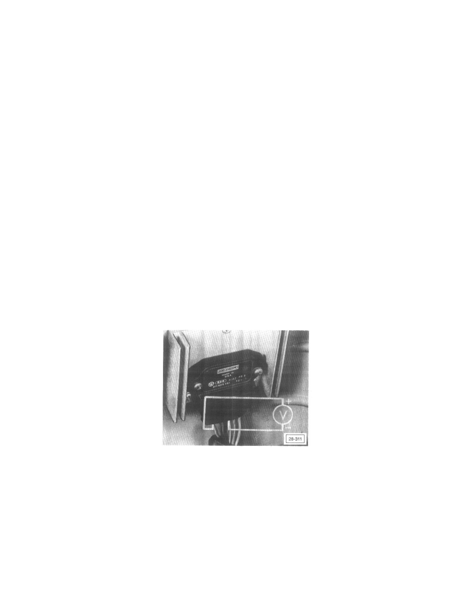
pull rubber boot from control unit connector (with connector connected) as shown
-
connect + (plus) wire of voltmeter (VAG 1315A or equivalent) to terminal 6 and - (minus) wire to terminal 3
-
turn ignition On
-
turn engine over slowly by hand (in running direction) and watch tester reading
Note: Position of Hall-generator aperture rotor (in distributor) changes when engine is turning.
Specifications:
-
0 to 0.7 volt primary current switch OFF - position of aperture rotor open to Hall generator
-
1.8 volt up to battery voltage primary current switched ON - position of aperture rotor-closed to Hall generator
if not, Hall generator is defective; replace