
A1
| Assembly sequence - dismantling and assembling complete gearbox |
| Removing and installing cover for gearbox housing, clutch housing, selector shaft with selector mechanism cover, input shaft, output shaft, differential and selector mechanism |

| Special tools and workshop equipment required |
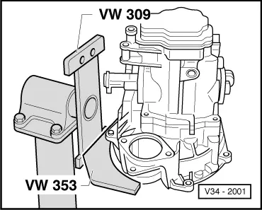
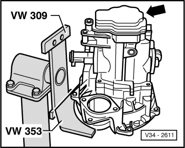
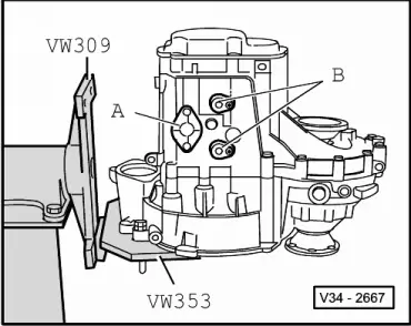
| t | Support plate -VW 309- |
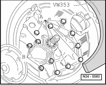
| t | Gearbox support -VW 353- |
| t | Drift -VW 295- |
| t | Drift sleeve -VW 244 B- |
| t | Hot air blower -V.A.G 1416- |
| t | Torque wrench -V.A.G 1331- |
| t | Stud M8 x 100 mm |

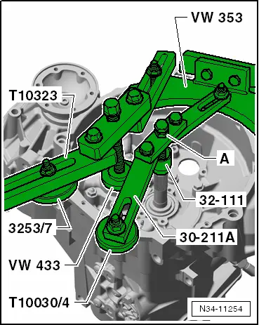
| t | Support bridge -30-211A- |
| t | Thrust piece -32 - 111- |
| t | Thrust piece of assembly tool -T10030/4- |
| t | Tube -VW 416 B- |
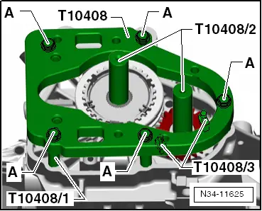
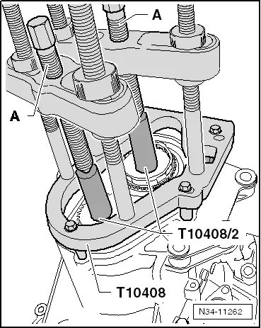
| t | Puller plate -T10408- |
| t | Spacers -T10408/1- |
| t | Thrust blocks -T10408/2- |
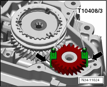
| t | Brackets -T10408/3- |

| t | Support bridge -T10323- |
| t | Assembly tool -3253/7- |
| t | Press tool -VW 433- |
| t | Torque wrench -V.A.G 1332- |
|
|
|
|
|
|
|
|
|
|
|
 Note
Note
|
|
|
|
|
|
|
|
|
|
|
|
Note
|
|
|
|
Note
|
|
|
|
|
|
|
|
|
|
|
|