audi Workshop Repair Guides

Audi Workshop Service and Repair Manuals

Removing and installing camshaft > < Checking axial clearance of camshaft
Removing and installing camshaft housing
Special tools and workshop equipment required
   
t  Threaded pins (2x) M6x70, e.g. -T10288/4- from centring tool -T10288-
  W00-10289
t  Locking pin -T10340-
  W00-10414
t  Camshaft clamp -T10414-
t  Electric drill with plastic brush attachment
t  Safety goggles
t  Sealant (2x) → Electronic parts catalogue
  W00-10823
Removing
–  Remove timing chain from camshaft chain sprocket → Chapter.
–  Remove turbocharger → Chapter.
–  Unplug electrical connector -1- at Hall sender -G40-.
  Note
Disregard -item 2-.
  A24-10803
–  Remove fuel rail → Removing and installing injectors; Rep. gr.24.
  N15-10563
–  Detach non-return valve -arrow- for crankcase breather system.
–  Pull oil dipstick out of guide tube.
  A15-10892
–  Slacken camshaft housing bolts in the sequence -L … A- and remove.
–  Carefully release camshaft housing from bonded joint and detach.
  N15-10570
Installing
Tightening torques
l  → Fig. „„Camshaft housing - tightening torque and sequence““.
l  → Chapter „Turbocharger - exploded view“.
l  Locking pin -T10340- is screwed into cylinder block as far as stop and tightened to 30 Nm.
l  Crankshaft is turned in normal direction of rotation until it makes contact with locking pin -T10340- = „TDC“ position.
  Caution
Protect lubrication system and bearings against contamination.
Cover exposed parts of the engine.
–  Remove old sealant from sealing surfaces.
  Caution
Protect lubrication system against contamination.
Cover exposed parts of the engine.
  A13-10525
  WARNING
Protect eyes against injuries.
Wear safety goggles.
–  Remove remaining sealant from camshaft housing and cylinder head using rotating plastic brush or similar.
–  Clean surfaces; they must be free of oil and grease.
  A13-0590
–  Screw 2 threaded pins M6x70 -item 1- (e.g. -T10288/4-) into cylinder head.
  Note
The threaded pins are used to position the camshaft housing correctly when installing. This prevents the roller rocker fingers from slipping off the compensation elements.
  N15-10568
–  Turn camshaft to „TDC“.
l  Grooves -arrows- on camshaft should be positioned as shown in illustration.
  N13-10381
–  Slide camshaft clamp -T10414- into camshaft housing as far as stop and screw bolt -1- in by hand until it makes contact.
  N15-10549
  Caution
Risk of leaks.
Different sealants must be used for the outer seal on the camshaft housing and for the seal at the camshaft bearing pedestals. For correct types of sealant refer to → Electronic parts catalogue.
  Note
Note the use-by date of the sealant.
–  For outer seal on camshaft housing: cut off nozzle of tube at front marking (nozzle Ø approx. 2 mm).
  A17-0081
  Caution
Make sure lubrication system is not clogged by excess sealant.
The bead of sealant must not be thicker than specified.
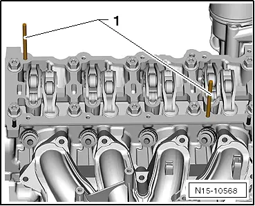
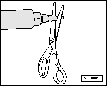
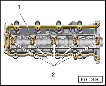
–  Apply bead of sealant -1- onto clean sealing surface of camshaft housing, as shown in illustration.
l  The bead of sealant must be 2.0 … 3.0 mm thick.
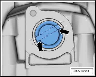
–  Apply a thin and even layer of sealant to clean sealing surfaces of camshaft housing (hatched areas -2- in illustration).
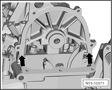
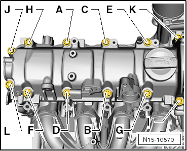
–  Make sure that all roller rocker fingers make contact with the valve ends correctly and are clipped into their respective support elements.
  Note
The camshaft housing must be installed within 5 minutes after applying the sealant.
  N15-10596
  Caution
Make sure remnants of oil are removed before fitting, otherwise leakage can occur.
Make sure sealing surfaces are free of oil when fitting camshaft housing.
–  Carefully lower camshaft housing vertically onto threaded pins -1- in cylinder head.
  Note
Make sure that camshaft housing is kept straight.
  N15-10568
–  Tighten camshaft housing bolts → Fig..
  N15-10570
  Caution
Risk of leaks.
Sealants for camshaft housing and timing chain cover (top) must not be allowed to mix.
–  Remove any excess sealant in area of -arrows-.
  Note
After fitting camshaft housing, allow sealant to dry for approx. 30 minutes.
Remaining installation steps are carried out in reverse sequence; note the following:
–  Install fuel rail → Removing and installing injectors; Rep. gr.24.
–  Install turbocharger → Chapter.
–  Install camshaft timing chain → Anchor.
  N15-10571

Removing and installing camshaft > < Checking axial clearance of camshaft