audi Workshop Repair Guides

Audi Workshop Service and Repair Manuals

Removing and installing turbocharger > < Removing and installing vacuum unit for turbocharger
Adjusting vacuum unit for turbocharger
   
Adjusting vacuum unit for turbocharger
Special tools and workshop equipment required
t  Universal dial gauge bracket -VW 387-
t  Hand vacuum pump -VAS 6213-
t  Pressure control valve -VAS 6342-
t  Turbocharger tester -V.A.G 1397A-
t  Dial gauge set, 4 pieces -VAS 6341-
t  Torque wrench -V.A.G 1783-

   
t  Hose clip pliers -VAS 6362-
  W00-10427
Procedure
–  Pull off engine cover panel (front) -arrows- and remove towards front.
  A10-11413
–  Remove bolts -arrows- and detach heat shield for turbocharger.
  N21-10220
–  Remove bolts -1 and 3-.
–  Release hose clip -2-, detach air pipe (top right) and remove air hose.
  A21-10567
–  Disconnect hose -arrow- from vacuum unit.
  N21-10118
–  Close lever -2- on pressure control valve -VAS 6342-.
–  Set up measuring equipment and testers as shown in illustration and connect to connection „II“ of turbocharger tester -V.A.G 1397A- and to vacuum unit for turbocharger.
–  Move adjuster ring -1- on hand vacuum pump -VAS 6213- to select „pressure“-arrow-.
  N21-10125
–  Switch on turbocharger tester -V.A.G 1397A- and set sliding switch to position „II“.
  V21-0096
–  Operate hand vacuum pump -VAS 6213- several times until the pressure is approx. 800 mbar.
  Caution
Risk of damage to vacuum unit on account of excessive pressure.
The pressure must not exceed 800 mbar.
–  Vent hand vacuum pump -VAS 6213--arrow A- to make sure the linkage of the charge pressure control in the turbocharger is free to move.
–  Repeat procedure 5 times.
  Note
This procedure should prevent the bypass flap and the vacuum unit linkage from sticking.
  N24-10282
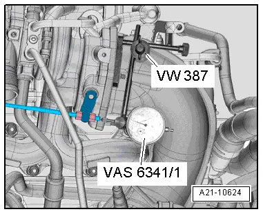
–  Attach dial gauge -VAS 6341/1- to universal dial gauge bracket -VW 387-.
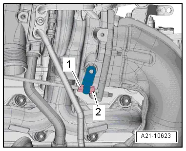
–  Secure universal dial gauge bracket -VW 387- to turbocharger as shown in illustration.
l  The dial gauge linkage must be in line with the linkage of the vacuum unit.
–  With pressure at 0 bar, set dial gauge -VAS 6341/1- to 1 mm preload.
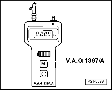
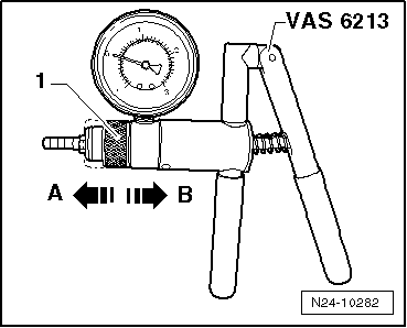
–  Operate hand vacuum pump -VAS 6213- several times until the pressure displayed on turbocharger tester -V.A.G 1397A- is approx. 800 mbar.
l  Specification on dial gauge -VAS 6341/1-: 1 mm travel
–  Vent system via pressure control valve -VAS 6342- so that pressure reading drops to 0 mbar.
Checking adjustment of vacuum unit
–  Set scale of dial gauge -VAS 6341/1- to „0“.
  Note
The following measurements must be performed in the specified sequence. Do not allow the pressure to drop to 0 between measurements.
–  Operate hand vacuum pump -VAS 6213- several times until a pressure of 500 ± 5 mbar is displayed on turbocharger tester -V.A.G 1397A-.
–  Read off and note travel indicated on dial gauge -VAS 6341/1-.
–  Operate hand vacuum pump -VAS 6213- several times until a pressure of 800 ± 5 mbar is displayed on turbocharger tester -V.A.G 1397A-.
–  Vent system via pressure control valve -VAS 6342- so that pressure reading drops to 500 ± 5 mbar.
–  Read off and note travel indicated on dial gauge -VAS 6341/1-.
–  Determine average value: add values „1“ and „2“ together and divide by 2.
l  Specification: 5.50 ± 0.25 mm.
  Note
  A21-10624
t  If reading does not match specification, loosen lock nut -1-.
t  Turn nut -2- until specification is obtained.
t  Tighten lock nut -1-.
–  When adjustment is correct, tighten lock nut -1- and secure with sealing paint.
Assembling
Installation is carried out in the reverse order; note the following:
Tightening torques
l  → Chapter „Turbocharger - exploded view“.
l  → Chapter „Charge air cooler - exploded view“.
  Note
t  Fit new O-rings.
t  Secure all hose connections with the correct type of hose clips (same as original equipment) → Electronic parts catalogue.
–  Install air pipe (top right) → Chapter.
–  Install air hoses with screw-type clips → Fig..
  A21-10623

Removing and installing turbocharger > < Removing and installing vacuum unit for turbocharger