audi Workshop Repair Guides

Audi Workshop Service and Repair Manuals

Stress-free alignment of exhaust system > < Silencer - exploded view
Removing and installing particulate filter
Special tools and workshop equipment required
   
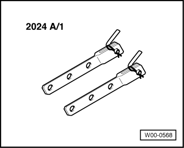
t  Hook -2024 A /1- of lifting tackle -2024 A-
  W00-0568
Removing
  Note
Fit all cable ties in the original positions when installing.
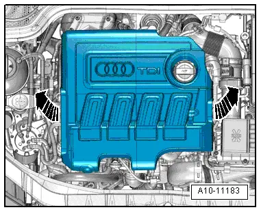
–  Remove engine cover panel -arrows-.
  A10-11183
–  Remove Lambda probe -G39- → Rep. gr.23.
–  Remove exhaust gas temperature sender 3 -G495- → Chapter.
–  Remove exhaust gas temperature sender 4 -G648- → Chapter.
–  Remove radiator cowl → Chapter.
–  Remove coolant pipes (right-side) → Chapter.
–  Remove heat shield for tunnel → Rep. gr.66.
–  Remove front wheel housing liner (right-side) → Rep. gr.66.
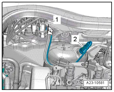
  A23-10581
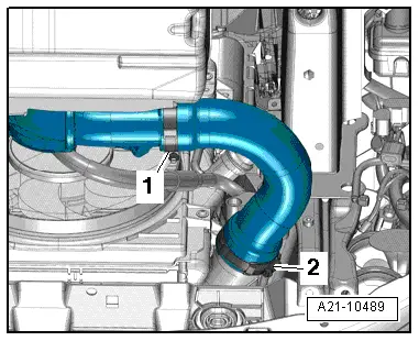
–  Release hose clips -1- and -2- and remove air hose.
–  Seal off open pipes/lines and connections with clean plugs from engine bung set -VAS 6122-.
  A21-10489
Vehicles with air conditioning:
–  Remove poly V-belt:
t  → Chapter „Removing and installing poly V-belt - vehicles with air conditioner compressor and tensioner“.
t  → Chapter „Removing and installing poly V-belt - vehicles with air conditioner compressor and tensioning roller“.
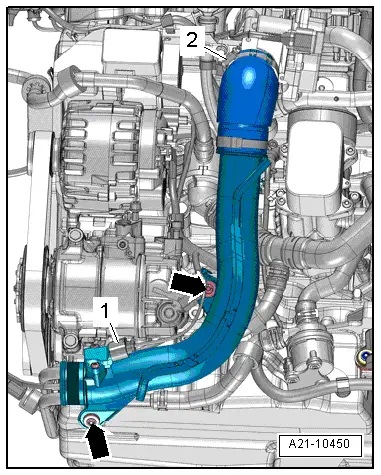
–  Remove bolts -arrows-.
–  Loosen hose clip -2-.
–  Unplug electrical connector -1- on charge pressure sender -G31-/intake air temperature sender -G42- and move clear electrical wiring.
–  Detach air pipe (right-side).
  A21-10450
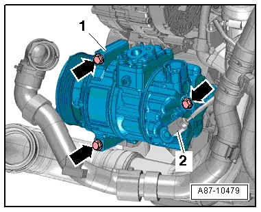
–  Unplug electrical connector -2- on air conditioner compressor regulating valve -N280-.
  Caution
Make sure that air conditioner compressor and refrigerant pipes and hoses are not damaged.
Do NOT stretch, kink or bend refrigerant lines and hoses.
–  Remove bolts -arrows-, detach air conditioner compressor -1- with pipe/hose assemblies connected and tie up to front.
  A87-10479
All vehicles (continued):
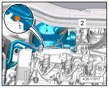
–  Remove bolt -1-.
–  Slacken bolt -2- and remove clamp.
  A26-11017
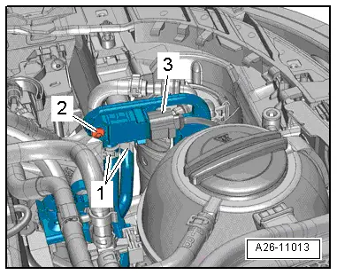
–  Unplug electrical connector -3-.
–  Unscrew bolt -2-, detach pressure differential sender -G505- and move clear hoses -1-.
  A26-11013
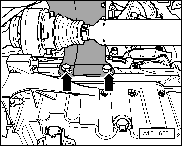
–  If fitted, remove bolts -arrows- and detach heat shield for drive shaft (right-side).
–  Unbolt drive shaft (right-side) from gearbox flange.
  A10-1633
  WARNING
Risk of accident.
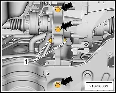
Do NOT loosen bolted connection -1-.
–  Remove bolts -top arrows-.
  Note
Disregard -bottom arrow-.
  N10-10308
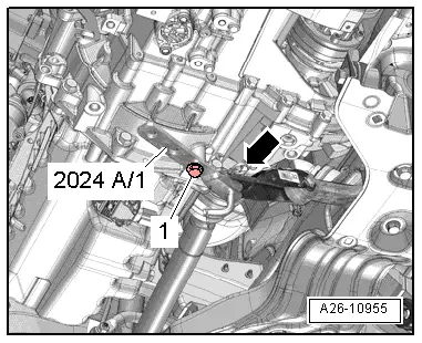
–  Press engine/gearbox assembly towards lock carrier and support using extension -2024 A /1-, as shown in illustration.
  WARNING
Accident risk from loose components of support bracket.
Secure retaining pin with locking pin -arrow- and extension -2024 A /1- with bolt -1- for pendulum support.
  A26-10955
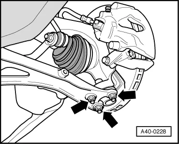
–  Unscrew nuts -arrows- for swivel joint (right-side).
–  Detach swivel joint (right-side) from wishbone.
  A40-0228
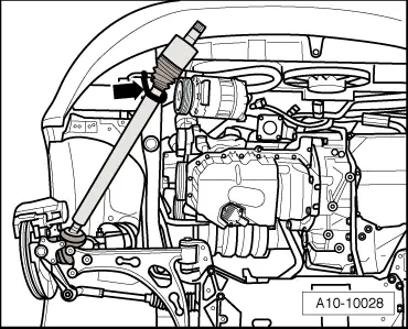
–  Pivot drive shaft (right-side) towards the front.
–  Tie up drive shaft to longitudinal member -arrow-.
  Note
Take care not to damage the surface coating of the drive shaft.
  A10-10028
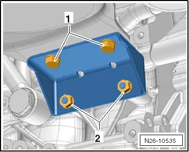
–  Remove bolts -1- and nuts -2- and detach bracket for particulate filter.
  N26-10535
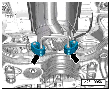
–  Pull particulate filter off mountings -arrows- and detach to the right.
Installing
Installation is carried out in the reverse order; note the following:
l  Tightening torques → Chapter „Silencer - exploded view“
  Note
Renew gaskets, self-locking nuts and clamp for particulate filter.
  A26-10956
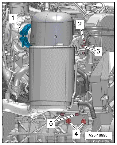
–  Note sequence when installing particulate filter:
  A26-10986
1.Fit particulate filter to turbocharger, attach clip -1- without tightening
2.Loosely screw in nuts -2, 4- and bolts -3, 5- by hand
l  It must still be possible to move particulate filter and bracket
3.Tighten clamp -1-
4.Tighten nuts -2, 4-
5.Tighten bolts -3, 5-

–  Install pendulum support → Rep. gr.34.
–  Install drive shaft (right-side) and swivel joint → Rep. gr.40.
–  Install heat shield for drive shaft → Anchor.
–  Install air conditioner compressor → Rep. gr.87.
–  Install poly V-belt:
t  → Chapter „Removing and installing poly V-belt - vehicles with air conditioner compressor and tensioner“.
t  → Chapter „Removing and installing poly V-belt - vehicles with air conditioner compressor and tensioning roller“.
–  Install air pipe → Chapter.
–  Install air hoses with screw-type clips → Fig..
–  Install front right wheel housing liner → Rep. gr.66.
–  Install heat shield for tunnel → Rep. gr.66.
–  Install coolant pipes (right-side) → Chapter.
–  Install radiator cowl → Chapter.
–  Install exhaust gas temperature sender 4 -G648- → Chapter.
–  Install exhaust gas temperature sender 3 -G495- → Chapter.
–  Install Lambda probe -G39- and pressure differential sender -G505- → Rep. gr.23.
–  Align the exhaust system so it is free of stress → Chapter.
–  After renewing particulate filter, perform "Adaption" in Guided Functions mode using → Vehicle diagnostic tester.
   

Stress-free alignment of exhaust system > < Silencer - exploded view