
A1
| Intake manifold (part 2) - exploded view |
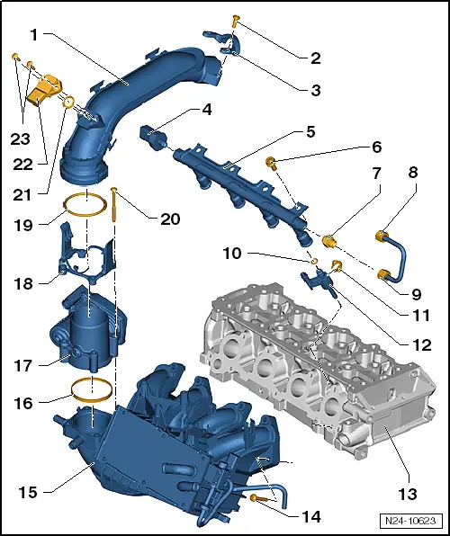
| 1 - | Pressure pipe |
| q | Use lubricant when installing |
| 2 - | Bolt |
| q | 7 Nm |
| 3 - | Retaining clip |
| 4 - | Fuel pressure sender -G247- |
| q | 22 Nm |
| q | Checking → Chapter |
| q | Removing and installing → Chapter |
| 5 - | Fuel rail |
| 6 - | Bolt |
| q | 20 Nm |
| 7 - | Adapter |
| q | 30 Nm |
| 8 - | High-pressure fuel pipe |
| q | 25 Nm |
| 9 - | High-pressure fuel pipe |
| q | 25 Nm |
| 10 - | O-ring |
| q | Renew |
| 11 - | Spring element |
| q | Check for correct fit on injector |
| 12 - | Injector, cylinder 1 -N30- |
| q | Injector, cylinder 2 -N31- |
| q | Injector, cylinder 3 -N32- |
| q | Injector, cylinder 4 -N33- |
| q | With teflon seal and support ring |
| q | Always renew teflon seal and support ring after removing injector |
| q | Removing and installing injectors → Chapter |
| 13 - | Cylinder head |
| 14 - | Bolt |
| q | 20 Nm |
| 15 - | Intake manifold |
| q | With intake manifold pressure sender -G71- (clipped onto intake manifold) |
| q | Removing and installing → Chapter |
| 16 - | Seal |
| q | Renew |
| 17 - | Throttle valve module -J338- |
| q | Removing and installing → Chapter |
| q | Cleaning → Chapter |
| q | Tighten to 7 Nm |
| q | When renewing, erase learnt values and adapt engine control unit -J623-, see vehicle diagnosis, testing and information system -VAS 5051B-, „Guided Functions“ |
| 18 - | Adapter |
| 19 - | O-ring |
| q | Renew |
| 20 - | Bolt |
| q | 7 Nm |
| 21 - | O-ring |
| q | Renew |
| 22 - | Charge pressure sender -G31- with intake air temperature sender 2 -G299- |
| q | Removing and installing → Rep. gr.21 |
| 23 - | Bolt |
| q | 5 Nm |