
A2
| Removing gearbox |

| Special tools and workshop equipment required |
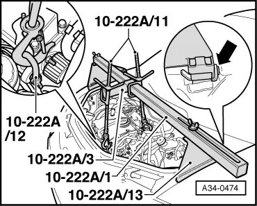
| t | Support bracket -10 - 222 A- |
| t | Adapter -10 - 222 A /3- |
| t | Shackle -10 - 222 A /12- |
| t | Adapter -10 - 222 A /13- |
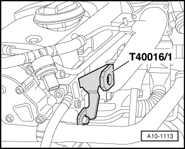
| t | Transportation shackle -T40016- |
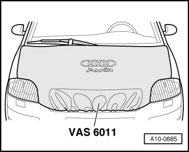
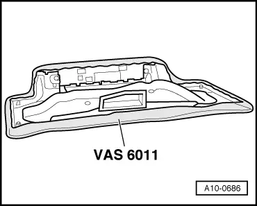
| t | Protective cover for bonnet Audi A2 -VAS 6011- |
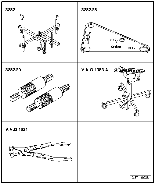
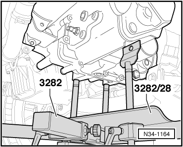
| t | Gearbox support -3282- |
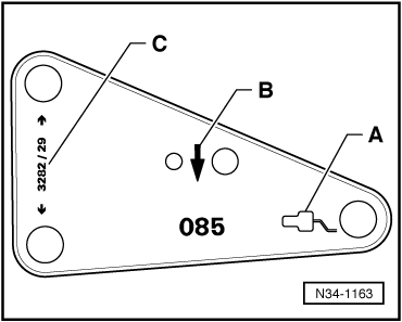
| t | Adjustment plate -3282/28- |
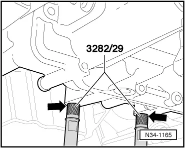
| t | Pin -3282/29- |
| t | Engine and gearbox jack -V.A.G 1383 A- |
| t | Hose clip pliers -V.A.G 1921- |
 Note
Note
|
 Caution
|
|
Note |
|
|
|
|
|
|
|
|
|
|
|
|
|
|
|
|
|
Note
|
|
|
|
|
|
|
|
|
|
|
|
Note |
|
|
|
|
|
|
|
|
|
Note
|
|
|
|
|
|
|
|
|
|
|
|
|
|