
A2
| Valve gear - exploded view of components |

| 1 - | 20 Nm + 90° (1/4 turn) further |
| q | Renew |
| q | Note correct sequence for loosening and tightening → Chapter „Removing and installing camshaft“ |
| 2 - | Rocker arm shaft |
| q | Note correct sequence for loosening and tightening → Chapter „Removing and installing camshaft“ |
| 3 - | Cylinder head bolt |
| q | Renew |
| q | Note correct sequence for loosening and tightening → Chapter „Removing and installing cylinder head“ |
| q | Before installing, insert washers in cylinder head → Item. |
| 4 - | Washer |
| q | For cylinder head bolts |
| 5 - | Hydraulic bucket tappet |
| q | Checking → Chapter |
| q | Removing and installing → Chapter „Removing and installing camshaft“ |
| q | Do not interchange (mark allocation) |
| q | Place down with contact surface facing downwards |
| q | Before installing check camshaft axial clearance → Fig. |
| q | Lubricate contact surface |
| 6 - | Valve cotters |
| 7 - | Valve spring plate |
| 8 - | Valve spring (outer) |
| q | Removing and installing with cylinder head installed → Chapter „Renewing valve stem oil seals“ |
| q | Remove and install with cylinder head removed using valve spring compressor -2037- |
| 9 - | Valve spring (inner) |
| q | Removing and installing with cylinder head installed → Chapter „Renewing valve stem oil seals“ |
| q | Remove and install with cylinder head removed using valve spring compressor -2037- |
| 10 - | Valve stem oil seal |
| q | Renewing → Chapter |
| 11 - | Valve guide |
| q | Checking → Chapter |
| 12 - | Unit injector |
| q | Removing and installing → Rep. Gr.23 |
| 13 - | Cylinder head |
| q | Machining valve seats → Chapter |
| 14 - | Oil seal |
| q | Renewing → Chapter |
| 15 - | Valves |
| q | Checking → Chapter |
| q | Valve dimensions → Chapter |
| q | Do not machine; only grinding in is permitted |
| 16 - | Bearing shell |
| q | Note installation position |
| q | Do not interchange used bearing shells (mark positions) |
| q | Make sure that the retaining lugs are correctly seated in the bearing caps and the cylinder head |
| 17 - | Camshaft |
| q | Check radial clearance with Plastigage |
| q | Radial clearance: wear limit: 0.11 mm |
| q | Runout: max. 0.01 mm |
| q | Checking axial clearance → Fig. |
| q | Removing and installing → Chapter |
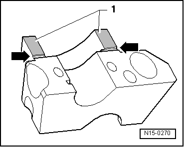
| 18 - | Bearing caps |
| q | Installation sequence → Chapter „Removing and installing camshaft“ |
| q | Bearing cap 4 is marked as bearing cap “5”. |
| q | Apply sealant to bearing caps 1 and 4 → Fig. |
| 19 - | 8 Nm + 90° (1/4 turn) further |
| q | Renew |
 Note
Note
|
|