
A2
| Oil filter bracket with oil cooler - exploded view |

| 1 - | Screw plug |
| q | 25 Nm |
| 2 - | Seal |
| q | Renew |
| 3 - | Oil cooler |
| q | Different versions |
| q | See note → Anchor |
| q | Diagram of coolant hose connections → Chapter |
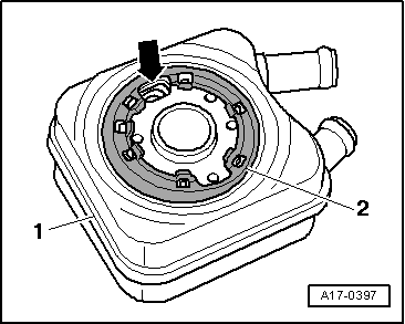
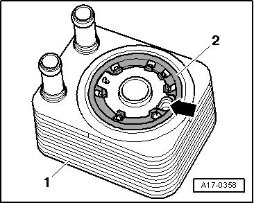
| 4 - | Seal |
| q | Renew |
| q | Installation position in vehicles with engine code letters AMF, BHC → Fig. |
| q | Installation position in vehicles with engine code letters ATL → Fig. |
| 5 - | Bolt |
| q | Renew |
| q | Tighten in diagonal sequence |
| q | 14 Nm + 90° (1/4 turn) further |
| 6 - | Gasket |
| q | Renew |
| 7 - | Oil filter bracket |
| q | With oil retention valve |
| q | The oil retention valve cannot be renewed separately |
| 8 - | Seal |
| q | Renew |
| 9 - | Oil pressure switch -F1- |
| q | Opening/closing pressure 0.7 bar |
| q | Brown insulation |
| q | Checking → Chapter |
| q | Removing and installing → Chapter |
| q | 20 Nm |
| 10 - | Sealing cap |
| q | 25 Nm |
| 11 - | O-ring |
| q | Renew |
| 12 - | Oil filter element |
| q | Detach from sealing cap -item 10- |
| q | Renew O-rings -item 11- and -item 13- when renewing filter |
| q | Note installation position |
| q | Observe change intervals → Booklet809 |
| 13 - | O-ring |
| q | Renew |
| 14 - | Oil supply pipe |
| q | To turbocharger |
| q | Note installation sequence: |
| – | First attach both ends of pipe loosely. |
| – | Then tighten connections on ends of pipe to 22 Nm. |
| – | Finally, secure bracket. |
| 15 - | Connection |
| 16 - | Seal |
| q | Renew |
|
|