
A3 Mk1
|
ABS/ESP ITT Mark 20 control unit and hydraulic unit
Removing and installing control unit and hydraulic unit
|
 |
|
|
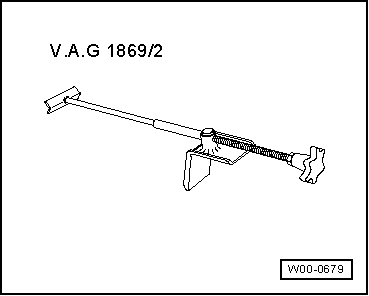
Special tools and workshop equipment required
|
 |
|
=> Parts List
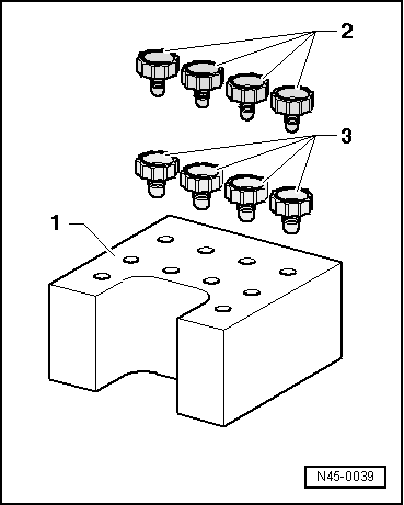
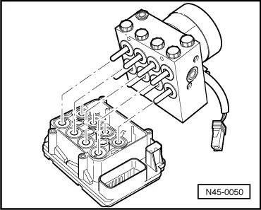
After separating control unit from hydraulic unit, always attach transportation protection for valve domes to hydraulic unit. No warranty claims can be accepted for hydraulic units not fitted with transportation protection for valve domes. |
 |
|
|
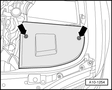
Removing
|
 |
|
|
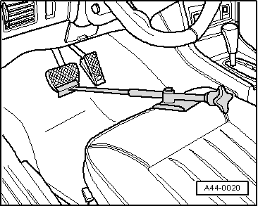 |
|
Note: This dissipates pressure in hydraulic unit.
|
 |
|
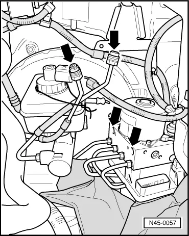
Notes:
|
 |
|
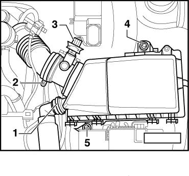
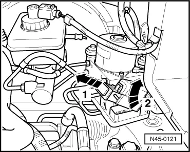
Attention:
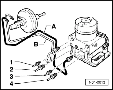
Take care not to bend brake pipes in the vicinity of the hydraulic unit.
|
 |
|
|
 |
|
|
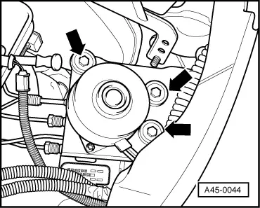
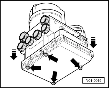
Unscrewing control unit from hydraulic unit
|
 |
||||||||||||||||
Note: Do not fully tighten bolts to facilitate attachment of individual brake pipes to hydraulic unit.
=> Running Gear, Self-diagnosis; Repair Group 01
=> Running Gear, Self-diagnosis; Repair Group 01 Note: Final control diagnosis can be used to establish whether pipe connections have been interchanged. Tightening torques
1) Replace bolts 2) For M10 and M12 connections | ||||||||||||||||