audi Workshop Repair Guides

Audi Workshop Service and Repair Manuals

Layout of components of refrigerant circuit and their influence on high-pressure and low-pressure sides|O-rings > < Refrigerant line with internal heat exchanger
Quick-release couplings on refrigerant line
  WARNING
Only release and open the quick-release couplings after completely discharging the refrigerant circuit.
  Note
t  This illustration shows the quick-release couplings with a refrigerant pipe with an internal heat exchanger as fitted for example on the Audi A4 2008 > and the Audi A5 Coupé 2008 > → Air conditioning; Rep. gr.87 (vehicle-specific workshop manual).
   
t  Removal of the refrigerant line -D- involves opening the retaining ring -A- with the refrigerant line release tool -T40149/- for example → Air conditioning; Rep. gr.87 (vehicle-specific workshop manual).
t  Following removal of the applicable refrigerant line, the quick-release couplings -B- and -G- are to be renewed together with the corresponding support ring -E- or -H- and the corresponding O-ring -F- or -J- → Air conditioning; Rep. gr.87 (vehicle-specific workshop manual) and → Electronic parts catalogue.
A - Retaining ring (in quick-release coupling, high-pressure side)
B - Quick-release coupling with retaining ring („high-pressure side“)
C - Refrigerant pipe with an internal heat exchanger
D - Refrigerant line („high-pressure side“)
E - Support ring („high-pressure side“)
F - O-ring („high-pressure side“)
G - Quick-release coupling with retaining ring („low-pressure side“)
H - Support ring („low-pressure side“)
J - O-ring („low-pressure side“)
  Note
  A87-10581
t  
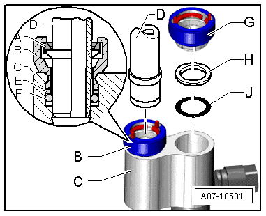
There are different versions of the quick-release couplings -A- and -D-. With both versions of these quick-release couplings, the refrigerant lines -C- can be released in the identical manner using the refrigerant line release tool -T40149/1- for example and removed.
t  
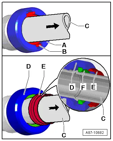
With the quick-release coupling -A- fitted at the start of production, the pins -B- become visible after fitting the refrigerant line -C- if the locked refrigerant line -C- is pulled in arrow direction.
t  With the quick-release coupling -D- installed from model year 2010 onwards (gradual introduction), the refrigerant line -C- is installed in the same way as with the quick-release coupling -A-. If, on this version, the refrigerant line -C- is pulled in the direction of the arrow after it is assembled, the snap ring -E- emerges from the quick-release coupling -D-, showing that the retaining ring -F- is completely locked onto the refrigerant line -C-. Subsequently the snap ring -E- must be detached from the refrigerant line -C-.
  A87-10682

Layout of components of refrigerant circuit and their influence on high-pressure and low-pressure sides|O-rings > < Refrigerant line with internal heat exchanger