|
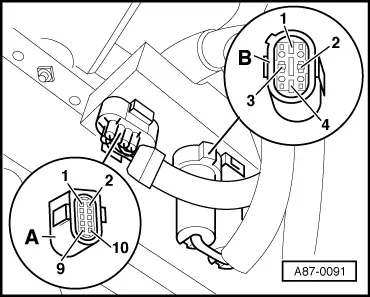
→ Pin assignment for air conditioner pressure switch -F129
Switch between contact 1 and 2 (opens in the event of vacuum and overpressure in the refrigerant circuit - the compressor is switched off)
Switch between contacts 3 and 4 (closes if pressure increases in the refrigerant circuit - the radiator fan is switched to 2nd speed)
Pin assignment at refrigerant temperature switch -F18 / -F54
Switch -F54 (between contact 1 and 2 closes at approx. 95 °C - the radiator fans are switched to 1st speed).
Switch -F18 (between contact 3 and 2 closes at approx. 102 °C - the radiator fans are switched to 2nd speed).
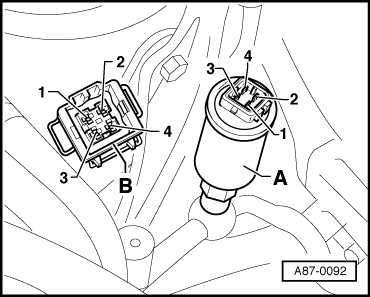
Refrigerant temperature control switch (too hot) -F14
Switch opens at approx. 118 °C - the compressor is switched off.
Note:
Only installed in vehicles with pressure switch -F129
=> Current Flow Diagrams, Electrical Fault-Finding and Fitting Locations
Test step 1 (voltage supply)
|
|
|---|
|
Select measuring range on hand-held multimeter V.A.G 1526:
Voltage measurement (20V =)
|
|
Test step
|
Contact at connector to -J293
|
Testing of
|
▪ Test conditions
- Additional operations
|
Specified value
|
Remedies if specified value not attained
|
|
1.1
|
Connector B contact 3
and
connector A, contact 6
|
Voltage supply
|
|
- approx. battery voltage
|
- Use current flow diagram to repair power supply and/or earth connection.
|
|
1.2
|
Connector B contact 4
and
connector A, contact 6
|
Voltage supply
|
|
- approx. battery voltage
|
- Use current flow diagram to repair power supply.
|
|
|
|---|
|
Select measuring range on hand-held multimeter V.A.G 1526:
Voltage measurement (20V =)
|
|
Test step
|
Contact at connector to -J293
|
Testing of
|
▪ Test conditions
- Additional operations
|
Specified value
|
Remedies if specified value not attained
|
|
1.3
|
Connector A contact 4
and
connector A, contact 6
|
Voltage supply
|
|
- approx. battery voltage
|
- Use current flow diagram to repair power supply.
|
|
1.4
|
Connector A contact 9
and
connector A, contact 6
|
Voltage supply
|
▪ Ignition on.
|
- approx. battery voltage
|
- Use current flow diagram to repair power supply.
|
Test step 2 (actuation of radiator fan)
|
|
|---|
|
Select measuring range on hand-held multimeter V.A.G 1526:
Voltage measurement (20V =)
|
|
Test step
|
Contact at connector to -J293
|
Testing of
|
▪ Test conditions
- Additional operations
|
Specified value
|
Remedies if specified value not attained
|
|
2.1
|
Connector A contact 5
and
connector A, contact 6
|
"Fan ON" signal from -E87 (1st speed from -E87).
|
▪ Engine running
Operating and display unit -E87 in "auto" mode (compressor on)
|
- approx. battery voltage
|
- Use circuit flow diagram to locate and rectify open circuit or short circuit to earth in the wiring between control unit
-J293 and -E87.
Renew operating and display unit -E87.
|
|
|
|---|
|
Select measuring range on hand-held multimeter V.A.G 1526:
Voltage measurement (20V =)
|
|
Test step
|
Contact at connector to -J293
|
Testing of
|
▪ Test conditions
- Additional operations
|
Specified value
|
Remedies if specified value not attained
|
|
2.2
|
Connector A contact 2
and
connector A, contact 6
|
"Fan ON" signal from -E87 (2nd speed from pressure switch -F129).
|
▪ Connector removed from pressure switch -F129, and contacts 3 and 4 jumpered
▪ Ignition on.
|
- approx. battery voltage
|
- Use current flow diagram to rectify voltage supply to pressure switch -F129.
Use current flow diagram to locate and eliminate open circuit in the wiring between pressure switch -F129 and control unit -J293.
|
|
|
|---|
|
Select measuring range on hand-held multimeter V.A.G 1526:
Voltage measurement (20V =)
|
|
Test step
|
Contact at connector to -J293
|
Testing of
|
▪ Test conditions
- Additional operations
|
Specified value
|
Remedies if specified value not attained
|
|
2.3
|
Connector A
and
connector B attached to -J293
|
Actuation of fan -V7 (speed 2) from pressure switch -F129.
|
▪ Ignition on.
▪ Connector detached from pressure switch -F129.
Contacts 3 and 4 jumpered (at connector to -F129).
|
- Radiator fan running at speed 2
|
- Use current flow diagram to rectify voltage supply to pressure switch -F129.
Use current flow diagram to locate and eliminate open circuit in the wiring between control unit -J293 and fans -V7.
Service radiator fan -V7.
Control unit -J293 defective - replace.
|
|
|
|---|
|
Select measuring range on hand-held multimeter V.A.G 1526:
Voltage measurement (20V =)
|
|
Test step
|
Contact at connector to -J293
|
Testing of
|
▪ Test conditions
- Additional operations
|
Specified value
|
Remedies if specified value not attained
|
|
2.4
|
Connector B contact 2
and
connector A, contact 6
|
"Fan ON" signal from -E87 (1st speed from temperature switch -F54).
|
▪ Connector detached from temperature switch -F18/-F54, and contacts 1 and 2 jumpered
▪ Ignition on.
|
- approx. battery voltage
Radiator fan running at speed 1
|
- Use current flow diagram to rectify voltage supply to temperature switch -F54.
Use current flow diagram to locate and eliminate open circuit in the wiring between temperature switch -F54 and control unit -J293.
Use current flow diagram to locate and eliminate open circuit in the wiring to fans -V7.
Service radiator fan -V7.
|
|
|
|---|
|
Select measuring range on hand-held multimeter V.A.G 1526:
Voltage measurement (20V =)
|
|
Test step
|
Contact at connector to -J293
|
Testing of
|
▪ Test conditions
- Additional operations
|
Specified value
|
Remedies if specified value not attained
|
|
2.5
|
Connector A contact 7
and
connector A, contact 6
|
"Fan ON" signal from -E87 (2nd speed from temperature switch -F18).
|
▪ Connector detached from temperature switch -F18/-F54, and contacts 2 and 3 jumpered
▪ Ignition on.
|
- approx. battery voltage
|
- Use current flow diagram to rectify voltage supply to temperature switch -F18.
Use current flow diagram to locate and eliminate open circuit in the wiring between temperature switch -F18 and control unit -J293.
|
|
|
|---|
|
Select measuring range on hand-held multimeter V.A.G 1526:
Voltage measurement (20V =)
|
|
Test step
|
Contact at connector to -J293
|
Testing of
|
▪ Test conditions
- Additional operations
|
Specified value
|
Remedies if specified value not attained
|
|
2.6
|
Connector A
and
connector B attached to -J293
|
"Fan ON" signal from -E87 (2nd speed from temperature switch -F18).
|
▪ Connector detached from temperature switch -F18/-F54, and contacts 2 and 3 jumpered
▪ Ignition on.
|
- Radiator fan running at speed 2
|
- Use current flow diagram to locate and eliminate open circuit in the wiring to fans -V7.
Service radiator fan -V7.
Control unit -J293 defective - replace.
|
Test step 3 (actuation of magnetic clutch)
|
|
|---|
|
Select measuring range on hand-held multimeter V.A.G 1526:
Voltage measurement (20V =)
|
|
Test step
|
Contact at connector to -J293
|
Testing of
|
▪ Test conditions
- Additional operations
|
Specified value
|
Remedies if specified value not attained
|
|
3.1
|
Connector A contact 8
and
connector A, contact 6
|
"Compressor ON" signal from -E87
|
▪ Engine running
▪ Operating and display unit -E87 in "auto" mode (compressor on)
▪ No compressor shutoff condition is displayed in the -E87 measured value block (display group 001).
|
- approx. battery voltage
|
- Use current flow diagram to locate and eliminate open circuit or short to positive or earth in the wiring between pressure switch -F129, temperature switch -F14 and control unit -J293.
Refrigerant temperature switch -F14 defective (open) or refrigerant too hot - check.
=> Current Flow Diagrams, Electrical Fault-Finding and Fitting Locations
|
|
|
|---|
|
Select measuring range on hand-held multimeter V.A.G 1526:
Current measurement (20 A=)
|
|
Test step
|
Contact at connector to -J293
|
Testing of
|
▪ Test conditions
- Additional operations
|
Specified value
|
Remedies if specified value not attained
|
|
3.2
|
Connector A contact 4
and
connector A, contact10
|
Actuation of air conditioner magnetic clutch -N25
|
▪ Ignition on.
|
- Less than 10 A
Magnetic clutch clicks (when applying voltage)
|
- Use current flow diagram to locate and eliminate open circuit or short to earth in the wiring between control unit -J293 and magnetic clutch -N25.
Open circuit in the earth connection to magnetic clutch -N25
=> Current Flow Diagrams, Electrical Fault-Finding and Fitting Locations
Magnetic clutch defective - rectify.
|
|