
A3 Mk1
|
|
|
|
|
 Caution
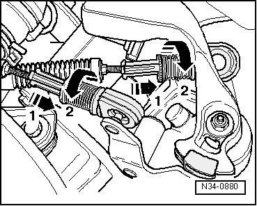
|
|
|
|
|
|
|
|
|
|
|
|
|
|
|
|
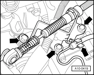
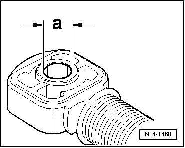
| Cable end-piece for: | Distance “a” |
| Gear selector cable to gearbox selector lever | 10 mm |
| Gate selector cable to relay lever | 8 mm |
|
|
|
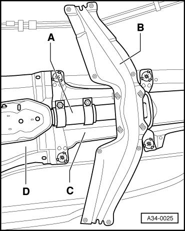
| Selector housing to body | 25 Nm | |
| Cross member to body | 25 Nm | |
| Selector cable support bracket to gearbox | 25 Nm | |
| Clamp for exhaust pipe | 40 Nm | |