A3 Mk1
|
 Note
Note
|
|
|
|
|
|
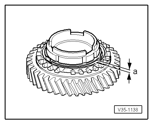
| Gap -a- | Installation depth | Wear limit |
| 1st gear | 0.75 ... 1.25 mm | 0.3 mm |
|
|
| Gap -a- | Installation depth | Wear limit |
| 1st gear | 1.2 ... 1.8 mm | 0.5 mm |
|
|
|
|

|
Note
|
|
|
|
|
|
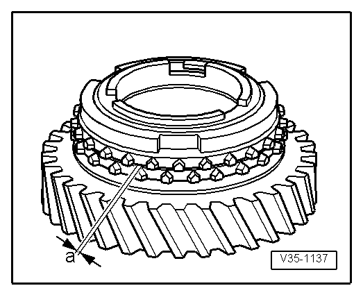
| Gap -a- | Installation depth | Wear limit |
| 1st gear | 0.75 ... 1.25 mm | 0.3 mm |
|
|
| Gap -a- | Installation depth | Wear limit |
| 1st gear | 1.2 ... 1.8 mm | 0.5 mm |
|
|
|
|