
A3 Mk1
| Exploded view - removing and installing gearbox housing and selector shaft |

| 1 - | Oval-head countersunk bolt |
| q | 15 Nm |
| q | M7 x 23 |
| q | 4x |
| q | Tensioning plate/grooved ball bearing to gearbox housing |
| 2 - | Bolt |
| q | 20 Nm |
| q | For reverse gear shaft |
| 3 - | Gearbox housing |
| q | Servicing → Chapter |
| q | From gearbox build date 03 08 8 onwards: with additional threaded hole for reversing light switch -F4- → Item |
| q | Installation of a gearbox housing with additional threaded hole for gearboxes up to gearbox build date 02 08 8 → Fig. |
| 4 - | Sealing cap |
| q | 50 Nm |
| 5 - | O-ring |
| q | Always renew |
| 6 - | Spring |
| q | Presses selector shaft and gearbox selector lever into gate for 3rd and 4th gear |
| 7 - | Selector shaft |
| q | Dismantling and assembling → Chapter |
| 8 - | Bolt |
| q | 25 Nm |
| q | M8 x 35 |
| q | 2x |
| q | Screw in below locking bolt → Item or → Item |
| 9 - | Reversing light switch -F4- |
| q | 23 Nm |
| q | Fitted from gearbox build date 03 08 8 onwards |
| 10 - | Locking bolt |
| q | 40 Nm |
| q | For selector shaft |
| q | Fitted from gearbox build date 03 08 8 onwards |
| q | Apply sealant -AMV 188 200 03- when installing |
| 11 - | Reversing light switch -F4- and locking bolt for selector shaft |
| q | 23 Nm |
| q | Fitted up to gearbox build date 02 08 8 |
| q | From gearbox build date 03 08 8, reversing light switch -F4- → Item and locking bolt → Item are supplied as two separate components → Fig. |
| q | Apply sealant -AMV 188 200 03- when installing |
| 12 - | Circlip |
| q | Holds tapered ring, thrust washer and spring in position when flange shaft is removed |
| 13 - | Tapered ring |
| q | With grooves to engage on thrust washer |
| q | Installation position: Taper towards differential cage |
| 14 - | Thrust washer |
| q | Installation position: Shoulder towards spring, lugs (if provided) towards tapered ring |
| 15 - | Spring |
| 16 - | Flange shaft |
| q | Removing and installing → Chapter |
| 17 - | Countersunk bolt |
| q | 25 Nm |
| 18 - | Bolt |
| q | 25 Nm |
| q | M8 x 52 |
| q | 12x |
| 19 - | Bolt |
| q | 5 Nm |
| q | For speedometer drive → Item |
| 20 - | Bracket |
| 21 - | Speedometer drive |
| 22 - | O-ring |
| q | Always renew |
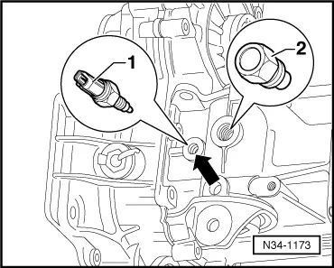
| Reversing light switch -F4--1-. | 25 Nm |
| Locking bolt -2- | 40 Nm |
|
|
|
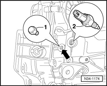
| Reversing light switch -F4--2-. | 25 Nm |
| Hexagon bolt M12 x 1.5 -1- | 25 Nm |