
A3 Mk1
|

| Special tools and workshop equipment required |
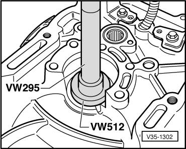
| t | Drift -VW 295- |
| t | Thrust pad -VW 512- |
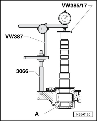
| t | Universal dial gauge bracket -VW 387- |
| t | End measuring plate -VW 385/17- |
| t | Spindle from assembly tool -3066- |
| t | Dial gauge |
|
|
|
|
|
|
|
|
 Note
Note
|
|
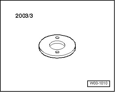
| Shim installed | 0.65 mm |
| + Measured value | 0.35 mm |
| + Preload (constant value) | 0.15 mm |
| Thickness of shim | 1.15 mm |
Note
|
|
| Thickness (mm) | Part No. |
| 0.65 0.70 | 020 311 391 P 020 311 391 Q |
| 0.75 0.80 0.85 | 020 311 391 020 311 391 A 020 311 391 B |
| 0.90 0.95 1.00 | 020 311 391 C 020 311 391 D 020 311 391 E |
| 1.05 1.10 1.15 | 020 311 391 F 020 311 391 G 020 311 391 H |
| 1.20 1.25 1.30 | 020 311 391 J 020 311 391 K 020 311 391 L |
| 1.35 1.40 | 020 311 391 M 020 311 391 N |
|