audi Workshop Repair Guides

Audi Workshop Service and Repair Manuals

Removing and installing gearbox > < Removing and installing selector mechanism
Adjusting selector mechanism
Special tools and workshop equipment required
   
t  Locking pin -T10027 A-
  Note
t  The following are prerequisites for correct gear lever alignment:
t  Gear selector linkage must be in proper condition and undamaged.
t  Selector mechanism must move freely.
t  The gearbox, clutch and clutch mechanism must also be in proper condition.
l  Gearbox in neutral.
Release cable end-pieces for gate selector cable and gear selector cable as follows:
  W00-10453
–  Pull locking mechanism on gear selector cable and gate selector cable forwards in direction of -arrow 1- as far as stop.
–  Then turn locking sleeve in direction of -arrow 2- as far as stop so that it clicks into place.
  Note
It should now be possible to move the cable in the cable end-piece.
  A34-0563
Lock the selector shaft as follows:
–  Press gearbox selector lever down (arrow -1-) into 1st/2nd gear gate and at the same time turn angled rod -A- approx. 90° in direction of arrow -2- so that it clicks into place.
The selector shaft is then locked and can no longer be moved.
  A34-0566
–  Pull the gear lever boot off the centre console -arrows-.
–  Pull boot up and over gear knob.
  A34-0026
–  If fitted, pull rubber cover far enough away from gear lever so you can insert locking pin -T10027- or -T10027 A- into hole -A- ( → Anchor).
  A34-0271
Now lock the gear lever as follows:
–  With gearbox in neutral, move gear lever to the left into 1st/2nd gear gate.
–  Then guide locking pin -T10027 A- through hole -A- and into hole -B-.
  Note
Ensure that gate selector cable and gear selector cable are located free of tension in selector cable end-pieces.
  N34-10814
–  Now turn locking mechanism on gear selector cable and gate selector cable to right as far as stop in direction of -arrow-.
The spring presses the locking mechanism into normal position.
  A34-0567
–  Now turn or pull out angled rod -A- back to original position (in direction of -arrow-).
t  The angled rod -A- should point vertically upwards.
  A34-0568
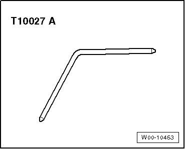
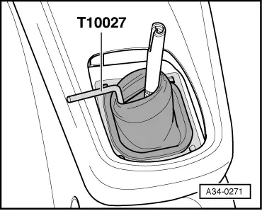
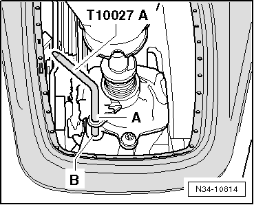
–  Pull pin -T10027 A- out of holes -A- and -B-.
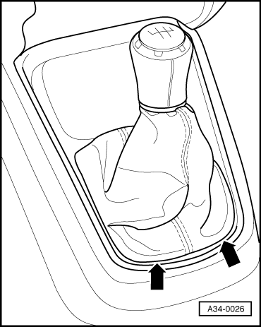
–  Install gear lever boot.
Function
l  With the gearbox in neutral, the gear lever should rest in the 3rd/4th gear gate.
–  Depress clutch.
–  Select all gears several times. Pay particular attention to the operation of the reverse gear locking mechanism.
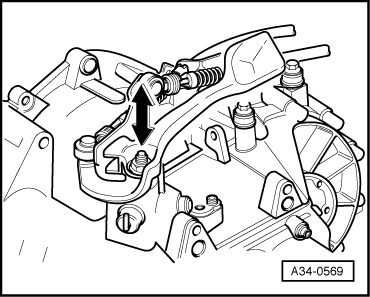
Should a gear fail to engage smoothly after repeated selection, check the play (lift movement) of the selector shaft as follows:
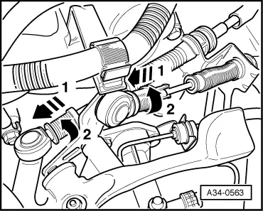
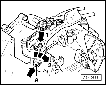
–  Engage 1st gear.
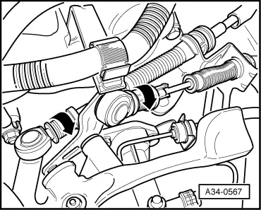
–  Push gear lever as far as it will go to the left and release.
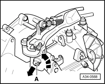
–  At the same time observe selector shaft on gearbox (2nd mechanic).
  N34-10814
–  The selector shaft should move up and down approx. 1 mm (in direction of -arrow-) when the gear lever is moved.
–  If this is not the case, adjust selector mechanism again → Chapter.
  A34-0569

Removing and installing gearbox > < Removing and installing selector mechanism