audi Workshop Repair Guides

Audi Workshop Service and Repair Manuals

Checking gearbox oil > < Transporting the gearbox
6-Speed manual gearbox 02M, Front-wheel drive
Removing and installing gearbox
Installing

Install in reverse sequence; note the following points:

Notes:

  • ◆ When performing repairs, renew seals, gaskets, self-locking nuts and bolts which have a specified tightening angle.
  • ◆ Secure all hose connections with hose clamps of the same type as those fitted at the factory.

=> Parts catalogue

  • ‒ Check whether the dowel sleeves for centralising engine/gearbox are in the cylinder block, install if necessary.
 
A10-0129
  • ‒ → Engage intermediate plate on sealing flange, and press onto dowel sleeves -arrows-.
  • ‒ Make sure that clutch plate is properly centred.
  • ‒ Clean input shaft splines and (in the case of used clutch plates) the hub splines. Remove corrosion and apply only a very thin coating of grease G 000 100 to the splines.

Note:

It must be possible to slide clutch plate easily back and forth on input shaft.

  • ‒ Check clutch release bearing (with hydraulic actuator) for wear, renew if necessary.
  • ‒ Lift the gearbox carefully and move it to the installation position with gearbox support 3282.
 
A34-0392
  • ‒ → Push the gearbox over the engine flywheel at the front side first -arrow 1-, and then at the rear side -arrow 2-.
  • ‒ Secure gearbox to engine.

Notes:

  • ◆ The tightening torques listed on this page apply only to lightly greased, oiled, phosphated, or black-finished nuts and bolts.
  • ◆ Additional lubricant such as engine or gearbox oil may be used, but do not use graphite lubricant.
  • ◆ Do not use degreased parts.
  • ◆ Tolerance for tightening torques is ±15%.

Tightening torques

 
A37-0214

→ Engine/gearbox mountings

Item

Bolt

Nm

1, 2

M12 x 55

80

3, 4

M12 x 165

80

5

M10 x 105

40

6, 7

M10 x 50

40

8

M12 x 70

80

A: centering sleeves

 
A34-0234
  • ‒ → Slide in cover plate -2- so that bottom lug engages on cylinder block, and secure at the top with bolt -1-.

Note:

Shown in illustration with gearbox removed.

  • ‒ Remove gearbox support 3282, engine support device 3300 A and support T10036.
 
A13-0383
  • ‒ → Use the left spindle to lift engine/gearbox assembly into installation position.

  • ‒ Use new bolts for securing.
 
A34-0231
  • ‒ → Install gearbox bracket on gearbox with bolts -1- (40 Nm + 90°).
  • ‒ Use new bolts for securing.
 
N34-0712
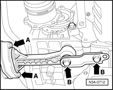
  • ‒ → Bolt pendulum support onto gearbox -arrows B-
    (40 Nm +1/4turn = 90°).
  • ‒ Then bolt pendulum support onto subframe -arrow A-
    (20 Nm +1/4turn = 90°).
  • ‒ Install exhaust system and align stress-free:

=> 4-Cylinder TDI®engine; Repair group 26; Removing and installing parts of exhaust system; Stress-free alignment of exhaust system - vehicles with front-wheel drive

  • ‒ Bolt drive shafts to gearbox
    (M10 Bolts; 77 Nm)
  • ‒ Fit right drive shaft guard (35 Nm).

The remaining installation steps are carried out in the reverse sequence.

  • ‒ Attach selector cables to gearbox and adjust=>Page34-20.
  • ‒ Bleed clutch system=>Page 30-20.
  • ‒ Electrical connections and routing:

=> Current flow diagrams, Electrical fault finding and Fitting locations binder

Note:

After connecting battery, activate the electrical equipment (radio, clock, electric window lifters) as described in the owner's manual.

Tightening torques

Components

Nm

Bolts/nuts

M6

10

M8

20

M10

45

M12

65

Except for the following:

Selector cable support bracket to gearbox

23

Checking gearbox oil > < Transporting the gearbox