
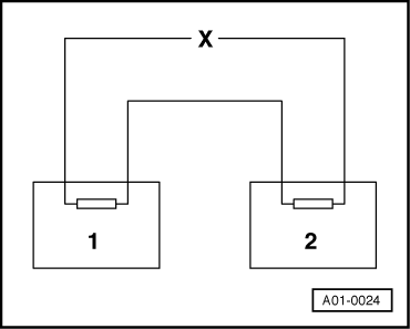
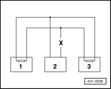
Testing a two-wire bus system for CAN databus functionality
 |
|
=> Current Flow Diagrams, Electrical fault Finding and Fitting Locations |
 |
|
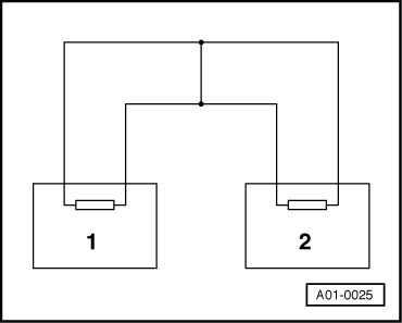
=> Current Flow Diagrams, Electrical fault Finding and Fitting Locations |
 |
|||||||||
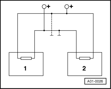
=> Current Flow Diagrams, Electrical fault Finding and Fitting Locations
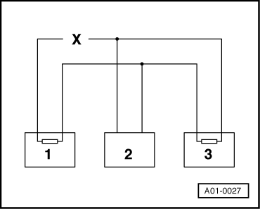
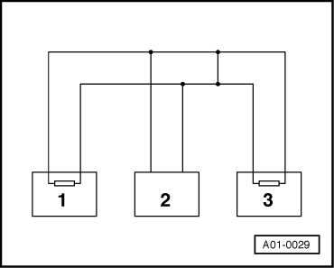
Example 2: From the faults present in the fault memories, you can see that control unit 2 has no connection to control units 1 or 3. |
 |
|||||||||
=> Current Flow Diagrams, Electrical fault Finding and Fitting Locations
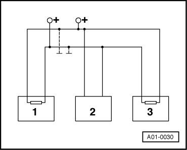
Example 3: From the faults present in the fault memories you can see that none of the control units are able to transmit or receive signals. |
 |
|||||||||
|
 |
|
|
=> Current Flow Diagrams, Electrical fault Finding and Fitting Locations
|