
A3 Mk1
 |
|
|
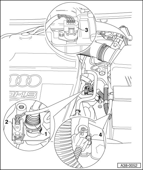
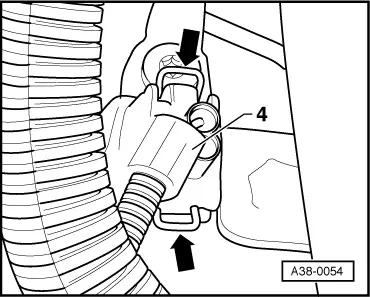
List of connectors which have to be disconnected for testing |
 |
|
|
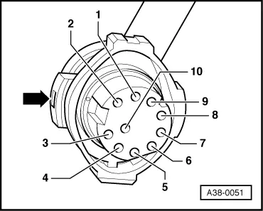
Testing wiring to 10-pin connector on valve body
|
 |
|||||||||||||||||||||||||||||||||||||||||||||||||
See the following table for resistance specifications.
Notes:
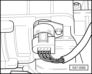
=> Automatic gearbox 01M; Repair group 38; Removing and installing valve body Testing wiring to multi-function switch (8-pin connector) | |||||||||||||||||||||||||||||||||||||||||||||||||
 |
|
|
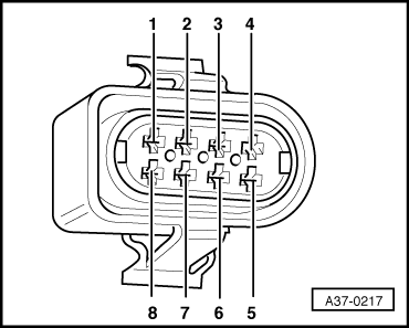 |
||||||||||||||||||||||||||||||||||||||||||||||||||||||
See the following two tables for resistance and voltage specifications.
Notes: | ||||||||||||||||||||||||||||||||||||||||||||||||||||||
|
|
|
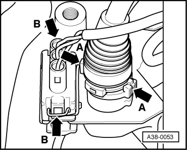
Testing wiring to road speed sender -G68 (3-pin connector)
|
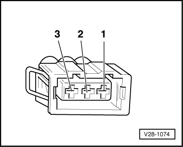 |
|||||||||||||||||||||
See the following table for resistance specifications.
Notes:
| |||||||||||||||||||||
 |
|
|
Testing wiring to gearbox speed sender -G38 (2-pin connector)
|
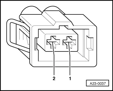 |
|||||||||||||||||
See the following table for resistance specifications.
Notes:
| |||||||||||||||||