
A3 Mk1
| Removing gearbox |

|

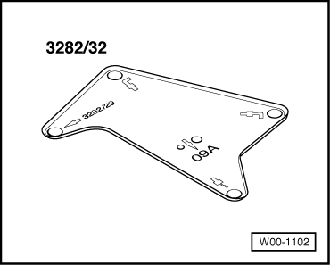
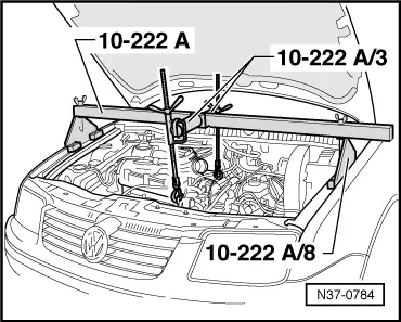
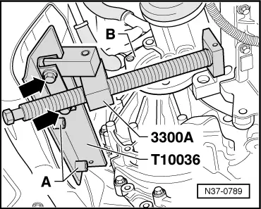
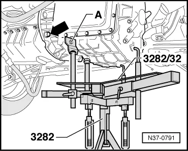
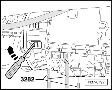
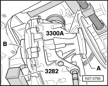
| t | Gearbox support -3282- |
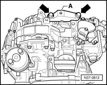
| t | Engine support -3300 A- |
| t | Support -T10036 A- |
| t | Torque wrench -V.A.G 1331- |
| t | Torque wrench -V.A.G 1332- |
| t | Engine and gearbox jack -V.A.G 1383 A- |
|
|
|
|
|
|
 Note
Note
Note
|
|
 Caution
|
|
Note
|
|
|
|
Note
|
|
|
|
|
|
|
|
|
|
|
|
|
|
|
|
|
|
|
|
Note
|
|
|
|
|
|
|
|
|
|
|
|