audi Workshop Repair Guides

Audi Workshop Service and Repair Manuals

Dismantling and assembling selector mechanism > < Checking ignition key removal lock
Removing and installing selector mechanism
Removing
–  Shift selector lever into position „P“.
  Caution
Follow steps required when disconnecting battery → Electrical system; Rep. gr.27.
  Note
Before continuing the procedure, the battery earth strap must be disconnected. First check whether a coded radio is fitted and obtain anti-theft coding if necessary.
–  With the ignition switched off, disconnect battery earth strap.
–  Remove selector lever handle → Chapter.
–  Remove centre console → General body repairs, interior; Rep. gr.68.
–  Disconnect locking cable from selector mechanism locking lever → Chapter.
   
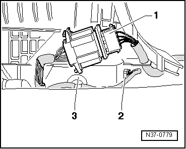
–  Unplug electrical connector -1- for printed circuit.
–  Use screwdriver to carefully pry retainer -3- on connector for selector lever lock solenoid -N110--2- out of shift unit.
–  Unplug connector -2- for selector lever lock solenoid -N110-.
  N37-0779
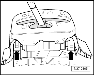
–  Carefully lever off four corners of frame -arrows- and remove.
–  Unscrew front shift unit mountings (two nuts).
  N37-0805
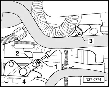
–  Pull selector lever cable -1- upwards off selector shaft lever -4-.
–  Remove securing clip -3- at cable support bracket.
  N37-0774
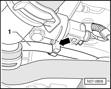
–  Unhook selector lever cable -1- from retainer -arrow- on engine.
–  Raise vehicle.
–  Unscrew retainer for catalytic converter at subframe and pull towards rear of vehicle; release double clamp → Engine, mechanics; Rep. gr.26.
The catalytic converter does not have to be removed; it can be left in place on the subframe.
–  Detach selector lever cable from bracket on heat shield (front).
–  Remove heat shield for tunnel (front).
–  Detach centre heat shield for tunnel and move towards rear.
  N37-0809
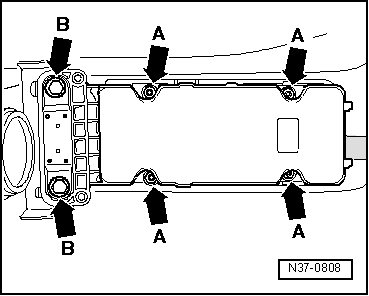
–  First unscrew four nuts -arrows A-.
–  Then unscrew two bolts -arrows B-.
–  Carefully push cover including protective sleeve forwards over selector lever cable.
  Note
Take care not to damage the protective sleeve.
  N37-0808
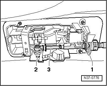
–  Lever selector lever cable -3- off selector lever -2- with a screwdriver.
–  Pull locking plate -1- securing selector lever cable to shift unit downwards and remove.
–  Carefully pull selector lever cable out of shift unit.
–  Remove shift unit completely from tunnel.
Installing
t  Check the protective sleeve for damage; the protective sleeve can only be renewed together with the selector lever cable.
t  Check that the protective sleeve is not twisted and is fitted correctly.
t  Do not bend or kink the selector lever cable.
l  Selector lever and selector shaft lever are in position „P“; both front wheels are locked (cannot be turned together in one direction).
  N37-0776
–  Guide selector lever cable -3- into shift unit and press onto selector lever -2-.
Installation position of selector lever cable:
The flat side of the selector lever cable bearing must be fitted onto the selector lever -2- first (towards the inside).
–  Fit new locking plate -1- for selector lever cable on shift unit.
Installation position of locking plate:
The angled end of the locking plate must point towards the end of the selector lever cable.
–  Insert complete selector mechanism with selector lever cable into tunnel from underneath.
  N37-0776
–  Screw in bolts -arrows B- by hand.
–  Secure front shift unit mountings (two nuts: 25 Nm).
–  Shift selector lever from position „P“ to „2“.
l  Selector mechanism and selector lever cable must move freely. If necessary renew selector lever cable or service selector mechanism.
–  Shift selector lever into position „P“.
  N37-0808
–  First tighten nuts -arrows A- to 10 Nm.
–  Then tighten two bolts -arrows B- to 25 Nm. When doing this check that gasket makes full contact.
–  Insert protective sleeve on selector lever cable in cover.
–  Install tunnel heat shields (front and centre).
–  Attach selector lever cable at bracket on heat shield (front).
–  Assemble exhaust system → Engine, mechanics; Rep. gr.26.
  N37-0808
–  Hook selector lever cable -1- into retainer -arrow- on engine.
  N37-0809
–  Loosen bolt -2- at the front ball socket of the selector lever cable -1-.
–  Insert selector lever cable in cable support bracket on gearbox and push onto selector shaft lever -4- using pliers.
–  Fit new securing clip -3- to selector lever cable at cable support bracket on gearbox.
  N37-0774
–  Carefully fit four corners of frame -arrows- and engage in position.
  N37-0805
–  Plug in connector -2- for selector lever lock solenoid -N110-.
–  Fit retainer -3- on connector for selector lever lock solenoid -N110- into shift unit.
–  Plug in electrical connector -1- for printed circuit.
–  Connect locking cable to locking lever on shift unit → Chapter.
–  Adjust locking cable → Chapter.
–  Check ignition key removal lock → Chapter.
–  Install centre console → General body repairs, interior; Rep. gr.68.
–  Install selector lever handle → Chapter.
–  Connect earth strap to battery (observe procedure required after connecting battery → Electrical system; Rep. gr.27).
–  Adjust selector lever cable → Chapter.
–  Check selector mechanism → Chapter.
  N37-0779

Dismantling and assembling selector mechanism > < Checking ignition key removal lock