
A3 Mk1
| Electrical/electronic components and fitting locations |

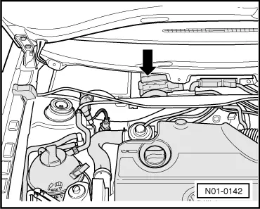
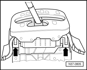
| 1 - | Automatic gearbox control unit -J217- |
| q | Fitting location → Fig. |
| q | Removing and installing → Chapter |
| q | Checked via self-diagnosis → Chapter |
| q | Control unit transmits and receives data via CAN bus → Chapter |
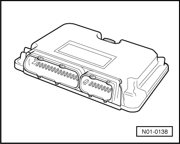
| 2 - | Engine control unit |
| q | Fitting location → Fig. |
| q | Removing and installing → Rep. gr.23 or → Rep. gr.24 |
| q | Control unit transmits and receives data via CAN bus → Chapter |
| q | If engine or gearbox control unit is renewed, system must be reset to basic setting → Chapter |
| 3 - | Dash panel insert with data bus diagnostic interface -J533- |
| q | With selector lever position display |
| q | Control unit transmits and receives data via CAN bus → Chapter |
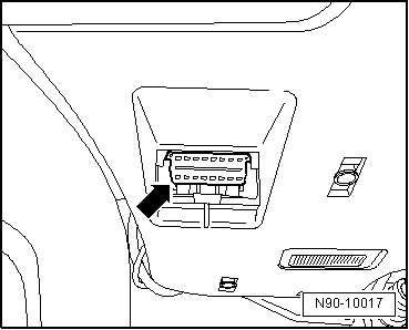
| 4 - | 16-pin connector -T16- (diagnostic connection) |
| q | Fitting location → Fig. |
| 5 - | Multifunction switch -F125- |
| q | Removing and installing, adjusting → Rep. gr.38 |
| q | Checked via self-diagnosis |
| 6 - | Intermediate shaft speed sender -G265- |
| q | Fitting location: in gearbox |
| q | Picks up signal on spur gear A |
| q | Checked via self-diagnosis |
| 7 - | Vehicle speed sender -G68- |
| q | Fitting location: in gearbox |
| q | Picks up gearbox output speed (road speed) |
| q | Checked via self-diagnosis |
| 8 - | Gearbox input speed sender -G182- |
| q | Fitting location: in gearbox |
| q | Picks up gearbox input speed (turbine shaft) |
| q | Checked via self-diagnosis |
| 9 - | Valve body |
| q | Fitting location: in gearbox → Rep. gr.38 |
| q | Following components are attached to valve body: |
| t | Solenoid valve 1 -N88- |
| t | Solenoid valve 2 -N89- |
| t | Solenoid valve 3 -N90- |
| t | Solenoid valve 4 -N91- |
| t | Solenoid valve 5 -N92- |
| t | Solenoid valve 6 -N93- |
| t | Solenoid valve 8 -N281- |
| t | Solenoid valve 10 -N283- |
| q | All components are checked via self-diagnosis |
| 10 - | Gearbox oil temperature sender (ATF) -G93- |
| q | Fitting location: in gearbox |
| 11 - | Selector lever lock solenoid -N110- |
| q | Fitting location, removing and installing → Rep. gr.37 |
| q | Checked via self-diagnosis |
| q | Can be checked by measured values → Chapter and in electrical check → Chapter |
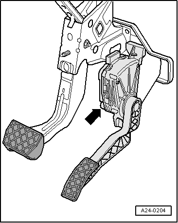
| 12 - | Brake pressure switch -F270- |
| q | Fitting location: switch is located on bulkhead in brake pipe to front wheel (right-side) |
| q | Signal can be tested by measured values → Chapter |
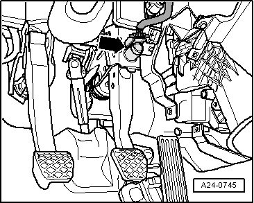
| 13 - | Brake light switch -F- |
| q | Fitting location → Fig. |
| q | Removing and installing → Brake system; Rep. gr.45 |
| q | Can be checked by measured values → Chapter and in electrical check → Chapter |
| 14 - | Starter inhibitor and reversing light relay -J226- |
| q | Fitting location: In central electrics → Current flow diagrams, Electrical fault finding and Fitting locations |
|
|
|
|
|
|
|
|
|
|
 Note
Note
|
|