audi Workshop Repair Guides

Audi Workshop Service and Repair Manuals

Installing cylinder head > < Removing and installing intake manifold
4-cyl. Diesel Direct Injection Engine (TDI), Mech. Components
Removing and installing cylinder head
Removing cylinder head
 
G15-0047

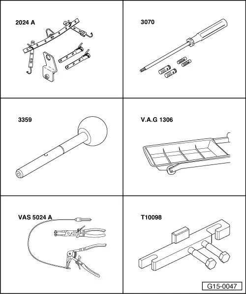
Special tools and workshop equipment required
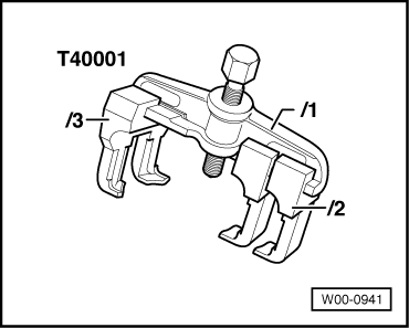
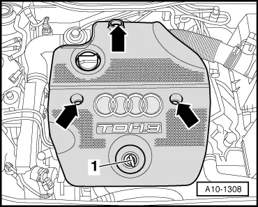
  • ◆ Lifting tackle 2024 A
  • ◆ Guide pin 3070
  • ◆ Pin 3359
  • ◆ V.A.G 1306
  • ◆ VAS 5024 A
  • ◆ Camshaft straightedge T10098
 
W00-0941
  • ◆ Two-arm puller T40001

Procedure

  • ● Engine in vehicle

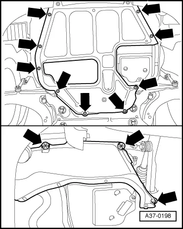
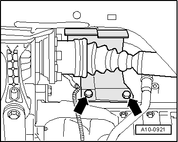
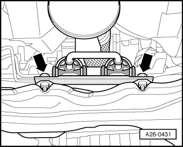
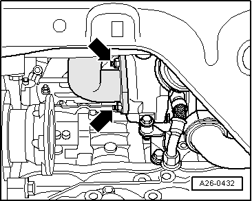
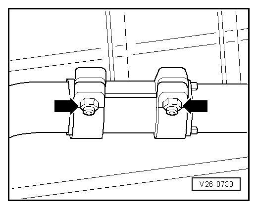
Note:

All cable ties which are released or cut open when removing must be fitted in the same position when installing.

  • ‒ Refer to coding on vehicles with encoded radio/radio navigation system (RNS); if necessary, interrogate.
  • ‒ With the ignition switched off disconnect the battery earth strap.
 
A10-1308
  • ‒ → Remove oil dipstick -1- from guide tube.
  • ‒ Unclip caps.
  • ‒ Unscrew nuts -arrows- and remove engine cover.
  • ‒ Reinsert oil dipstick in guide tube.
 
A10-0396
Important
Hot steam or hot coolant can escape when opening expansion tank. Cover cap with a cloth and open carefully.
  • ‒ Open the cover of the coolant expansion tank
  • ‒ → Remove lower air duct pipe -arrows-.

 
A37-0198
  • ‒ → Remove noise insulation in centre and on right -arrows-.
 
A10-0122

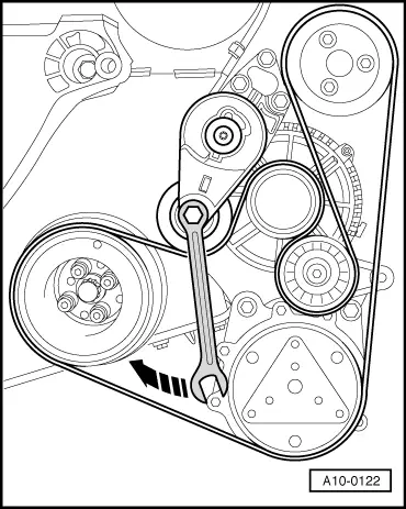
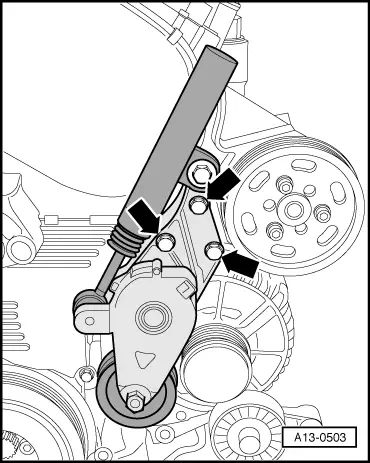
Note:

Mark the running direction with chalk or a felt-tipped pen before removing the ribbed belt. If the belt runs in the opposite direction when it is refitted, this can cause breakage.

  • ‒ Fit flat 16 mm box wrench at hexagon of tensioner.
  • ‒ → Swivel tensioning roller in direction of arrow to slacken ribbed belt.
  • ‒ Remove ribbed belt.

 
A10-0118
  • ‒ Place drip tray V.A.G 1306 below engine.
  • ‒ → Turn drain plug -arrow- on radiator anti-clockwise. If necessary, fit drain hose on connection.
 
A10-0119
  • ‒ → Also disconnect lower coolant hose on oil cooler -arrow-, and drain off remaining coolant.

 
A10-0921
  • ‒ → Unbolt heat shield for right drive shaft -arrows-.
 
A26-0431
  • ‒ → Unbolt bracket for exhaust system from assembly mounting -arrows-.

 
A26-0432

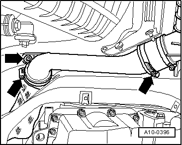
Note:

The isolating element in front exhaust pipe must not be deflected more than 10° to avoid damage..

  • ‒ → Unscrew securing bolts -arrows- of front exhaust pipe/exhaust turbocharger.
 
V26-0733
  • ‒ → Detach the exhaust system at the clamping sleeve -arrows-.
  • ‒ Remove the front exhaust pipe.

 
A21-0257
  • ‒ → Remove air duct hoses -2- and -3- from turbocharger.
  • ‒ Unscrew turbocharger bracket -1-.
  • ‒ Remove oil return pipe -4- at cylinder block.
 
A13-0502
  • ‒ Detach the cover and the electrical connector at the right headlight unit.
  • ‒ → Disconnect fuel-feed line -2- and fuel-return line -1- at injection pump.
  • ‒ Disconnect the electrical connection -3- at the sender -G71/-G72.
  • ‒ Expose the wiring at the air duct pipe.
  • ‒ Remove the air duct pipe on right side -arrows-.

 
A15-0740
  • ‒ → Pull off the vacuum hoses -2- at the exhaust gas recirculation valve or at the Y-piece -4-, respectively.
  • ‒ Disconnect electrical connector for heating resistance (crankcase ventilation system) -N79 -Item 3-.
  • ‒ Disconnect hose -6- to air cleaner housing.
  • ‒ Pull crankcase ventilation pipe -7- off rear of air duct pipe.
  • ‒ Unscrew bolts -1- and -5- and remove the air duct pipe at rear.
 
A10-1315
  • ‒ → Remove the vacuum hose -arrow- and expose the vacuum hose.
 
A10-0933
  • ‒ → Remove air duct hose -1- from air duct pipe.
  • ‒ Detach connector of air mass meter -3-.
  • ‒ Unscrew bolts -4- and -5-.
  • ‒ Remove vent hose -2- from rear of air cleaner housing.
  • ‒ Take out air cleaner housing.

 
A21-0185
  • ‒ → Unscrew oil feed pipe from exhaust turbocharger and exhaust manifold -arrows-.
 
A15-0528
  • ‒ → Unscrew oil feed line from oil filter bracket -arrow- and also on cylinder head and lay line aside.

 
A10-1310
  • ‒ → Disconnect the electrical connections at the glow plugs (coolant) -Q7 -Item 4- (manual gearbox only).
  • ‒ Disconnect the electrical connection -7- at the coolant temperature sender -G62 and expose wiring.
  • ‒ Pull vacuum pipe -5- off at exhauster.
  • ‒ Detach the coolant hoses -1-, -2-, -6- and -8-.
  • ‒ Remove injector pipes.

Note:

Always remove complete pipe set. Use injector pipe spanner 3035.

  • ‒ Detach injector/injection pump return line.
  • ‒ Detach glow plug connector console.
  • ‒ Take needle lift sender electrical connection from bracket and disconnect it.
 
A13-0503
  • ‒ → Remove tensioner for ribbed belt -arrows-.
  • ‒ Remove upper toothed belt guard.
  • ‒ Unscrew 2 toothed belt guard bolts at rear on both sides of the cylinder head.
 
A13-0045
  • ‒ → Turn crankshaft to TDC No. 1 cylinder -arrow- (vehicles with manual gearbox).

 
A13-0043
  • ‒ → Turn crankshaft to TDC No. 1 cylinder -arrow- (vehicles with automatic gearbox).

Note:

Position crankshaft to TDC No. 1 cylinder 1 with engine removed.

 
N15-0461
  • ‒ Remove the exhauster => Fig.15-8.
  • ‒ → Turn the bolts -1- by hand up to stop into the cylinder head.
  • ‒ Lock the camshaft using camshaft straightedge T10098 as shown in the illustration.
  • ‒ If the camshaft straightedge T10098 cannot be inserted, rotate crankshaft 1 additional turn (360°).

 
A13-0052
  • ‒ → Lock injection pump sprocket using pin 3359.
  • ‒ Loosen injection pump sprocket securing bolts -arrows-.
 
A23-0044

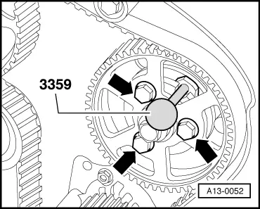
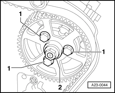
Note:

→ Never loosen the injection pump sprocket central nut -2-. Otherwise the injection pump basic setting is incorrectly adjusted and cannot be corrected again using workshop equipment.
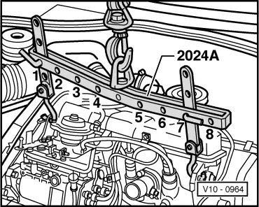
 
A13-0504
  • ‒ → Unscrew the tensioning roller nut -arrow-.
 
M13-0002
  • ‒ Remove the toothed belt from the camshaft toothed belt sprocket.
  • ‒ → Unscrew the camshaft sprocket bolt by one half turn .
  • ‒ Place the two-arm puller T40001 with claw T40001/2 -Item A- and the two-arm claw T40001/3 -Item B- centralised onto the camshaft sprocket.
  • ‒ Pull off the camshaft sprocket using the two-arm puller. Counterhold using an open-end spanner -C- in the process.
  • ‒ Removing camshaft toothed belt sprocket.
  • ‒ Remove cylinder head cover => Page 15-9.
 
N15-0026
  • ‒ → Loosen cylinder head bolts in the sequence 1 ... 10.
 
V10-0964
  • ‒ → Attach lifting tackle 2024 A on cylinder head.
Important
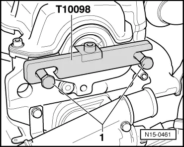
The hook attachments and locating pins on the lifting tackle must be secured with locking pins.

Note:

In addition, tie intake manifold to lifting tackle eye in order to obtain a stable centre of gravity position for the cylinder head.

  • ‒ Slightly lift cylinder head using workshop crane.
  • ‒ Simultaneously move cylinder head to the left out of rear of toothed belt guard and remove tensioning roller.

Installing cylinder head > < Removing and installing intake manifold