audi Workshop Repair Guides

Audi Workshop Service and Repair Manuals

Adjusting engine mounting > < Attaching engine to repair stand
4-cyl TDI®-Engine, Mechanical Components
Removing and installing engine -vehicles with four-wheel drive-
Installing

Procedure

  • ● Engine installed on engine bracket T10012.

Installation is carried out in the reverse order; note the following:

Notes:

  • ◆ When performing installation procedures always replace self-locking nuts and bolts.
  • ◆ Replace seals, gaskets, and bolts which have a specified tightening angle.
  • ◆ Hose connections and hoses for charge air system must be free of oil and grease before assembly.
  • ◆ Secure all hose connections with the correct hose clamps (same as original equipment):

=> Parts List

  • ‒ Check whether the dowel sleeves for centralising engine/gearbox are in the cylinder block, install if necessary.
 
A10-0129
  • ‒ → Engage intermediate plate on sealing flange and push onto dowel sleeves -arrows-.
  • ‒ If necessary, check that clutch plate is properly centred.
  • ‒ Check clutch release bearing for wear, renew if necessary.
  • ‒ Lightly lubricate clutch release bearing, release bearing guide sleeve and splines on input shaft with G 000 100.
  • ‒ Bolt gearbox to engine, use new bolts to fasten.

Notes:

  • ◆ The tightening torques listed on this page apply only to lightly greased, oiled, phosphated, or black finished nuts and bolts.
  • ◆ Additional lubricant such as engine or gearbox oil may be used, but do not use graphite lubricant.
  • ◆ Do not use degreased parts.
  • ◆ Tightening torque tolerance ±15%.
 
A37-0214

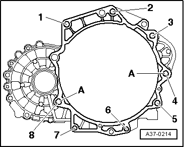
Vehicles with manual gearbox 02M:

→ Fastening engine to gearbox

Item

Bolt

Nm

1, 2 1)

M12 x 55

80 2)

3 1), 4 1)

M12 x 165

80 2)

5

M10 x 105

45 2)

6, 7

M10 x 50

45 2)

8

M12 x 70

80 2)

    1)    Bolt with threaded pin M8

    2)    Replace bolts

A: Centring sleeves

 
A34-0234
  • ‒ → Push in splash plate -2- in such a way that the lower lug engages into the cylinder block and secure on top with bolt -1-.
 
A10-1367
  • ‒ → Install angle drive mounting, observe the following installation sequence:
    • ‒ Fit bolts -4 ... 6- loosely.
    • ‒ Initially tighten bolts -1 ... 3- to 3 Nm.
    • ‒ Then tighten bolts -4- and -6- to 45 Nm.
    • ‒ Tighten bolt -5- to 22 Nm.
    • ‒ Tighten bolts -1 ... 3- to 45 Nm.

 
A10-0125
  • ‒ Guide engine/gearbox assembly into the chassis.
  • ‒ → Unscrew bolts -arrows- engine mounting from engine console...
 
A10-0126
  • ‒ → ...and gearbox mounting on gearbox console hand tight.
  • ‒ Only use new bolts to secure.

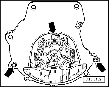
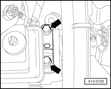
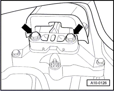
Note:

The bolts are tightened to final torque only after adjusting the engine mounting => Page 10-85.
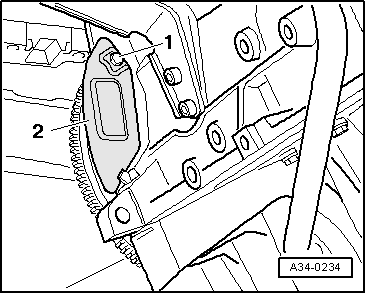
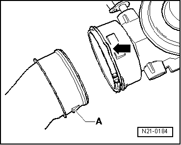
  • ‒ Remove engine mounting T10012 from engine.

 
V39-1817
  • ‒ → Push mechanical engine/gearbox units against bulkhead; the lug of the angle drive must be inserted horizontally and carefully into the flange of the propshaft.
Important
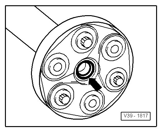
The sealing ring -arrow- in the flange of the propshaft may not be damaged when removing and installing the mechanical units of the engine/gearbox. If sealing ring is damaged propshaft must be replaced.
 
V34-2101
  • ‒ → Bolt on propshaft with drive disc to the flange of the angle drive
    -arrows-. Tightening torques:

=> 5 and 6-speed Manual Gearbox-02M Four-wheel Drive/Final Drives; Repair group 39

  • ‒ Fit front exhaust pipe to turbocharger and secure with nut.
  • ‒ Installing subframe

=> Running Gear, FWD and 4WD; Repair group 40

 
N34-0712
  • ‒ → First attach pendulum support to gearbox -arrows B- and then to subframe -arrows A-.
  • ‒ Only use new bolts to secure.
  • ‒ Install drive shafts.

=> Running Gear, FWD and 4WD; Repair group 40

  • ‒ To facilitate the attachment of the alternator, vane pump and air conditioner slightly push back the bush for the securing bolt.
 
A10-0937
  • ‒ → Push the pressure line -1- into the hose connector and lock it with the catch.
Important
The clutch pedal must not be operated before the clutch system has been bled.
  • ‒ Remove hose clamp -3094-.
  • ‒ Bleeding clutch hydraulic system:

=> 5 and 6-speed Manual Gearbox 02M Four-wheel Drive/Gearbox; Repair group 30; Servicing clutch mechanism

  • ‒ Attach selector cables to gearbox and adjust:

=> 5 and 6-speed Manual Gearbox 02M Four-wheel Drive/Gearbox; Repair group 34; Servicing clutch mechanism

  • ‒ Install exhaust system and align it stress-free => Page 26-35.
  • ‒ Install ribbed belt =>Page 13-12.
  • ‒ Adjust engine mounting => Page 10-85.
 
N21-0184
  • ‒ → When installing air duct pipes with connectors, ensure that the securing clip -arrow- engages audibly in the retaining lug -A-.
  • ‒ Install vacuum hoses =>as of Page 21-21.
  • ‒ Electrical connections and routing:

=> Current Flow Diagrams, Electrical Fault-finding and Fitting Locations binder

Notes:

  • ◆ If the battery is reconnected, please ensure that the vehicle equipment (radio, radio/navigation system, clock, electric window lifters) is activated as described in the operating instructions.
  • ◆ Deactivate the service mode of the telematics control unit.

=> Radio, Telephone and Navigation System; Repair group 91

  • ‒ Check oil level => Page 17-23.
Important
Do not use charging unit for boost starting. There is danger of damaging the vehicle control units.
  • ‒ Top up coolant => Page 19-10.

Notes:

  • ◆ Drained coolant may only be used again if the original cylinder head and cylinder block are re installed.
  • ◆ Coolant must not be used again if it is dirty.

Tightening torques

Component

Nm

Bolts/nuts

M6

10

M8

20

M10

45

M12

65

Except for the following:

Pendulum support to gearbox

40 + 90° 1)2)

Pendulum support to subframe

20 + 90°1)2)

Vane pump for power steering pump to bracket for auxiliary assemblies


23

    1)    Stretch bolts, replace

    2)    90°corresponds to a quarter of a turn

Component

Nm

Air conditioner compressor to bracket for auxiliary mechanical units


45

Alternator to bracket for auxiliary mechanical units


23

Resonator to turbocharger

9

Selector cable support bracket to gearbox

23

Adjusting engine mounting > < Attaching engine to repair stand