
A3 Mk1
|
Removing and installing engine - Vehicles with front-wheel drive
Removing
Notes:
Important
|
 |
|
Important
Hot steam can escape when opening cap on expansion tank: Cover cap with a cloth and open carefully.
|
 |
|
|
 |
|
|
 |
|
|
 |
|
|
 |
|
Vehicles with drain plug:
All models:
|
 |
|
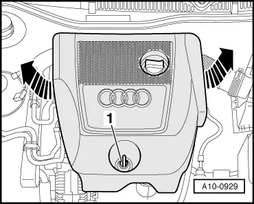
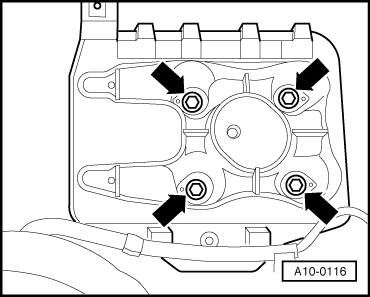
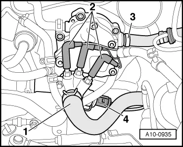
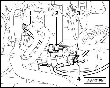
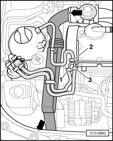
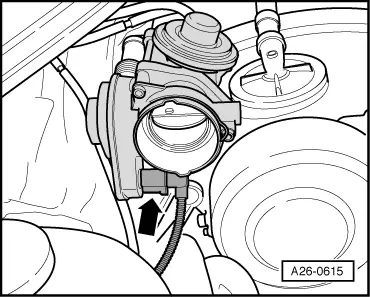
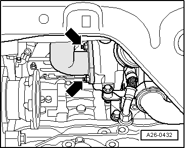
Note: Illustration shows an engine with code ASZ. |
 |
|
|
 |
|
|
 |
|
|
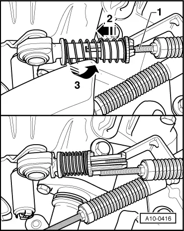
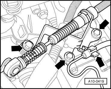
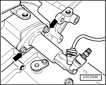
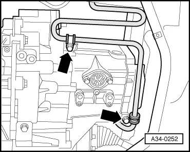
Vehicles with manual gearbox: Detach both gear selector cables from gearbox as follows:
|
 |
|
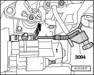
Vehicles with engine code ATD, AXR:
|
 |
|
|
 |
|
Important
Do not depress clutch pedal after removing slave cylinder. |
 |
|
|
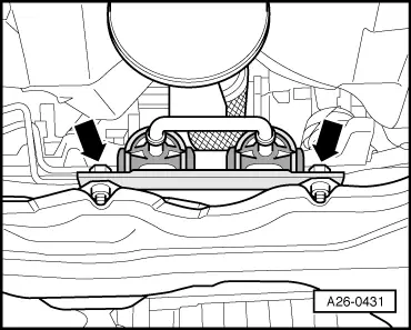
Vehicles with engine code ASZ, ATD:
All models:
|
 |
|
|
 |
|
|
 |
|
|
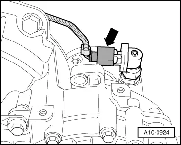
Vehicles with engine code ASZ:
|
 |
|
|
All models:
|
 |
|
|
 |
|
|
 |
|
|
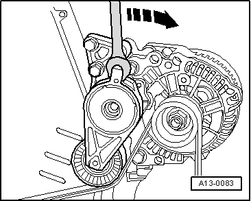
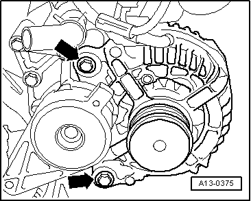
Note: Mark the running direction with chalk or a felt-tipped pen before removing the ribbed belt. If the belt runs in the opposite direction when it is refitted, this can cause breakage.
|
 |
|
|
 |
|
|
 |
|
|
 |
|
|
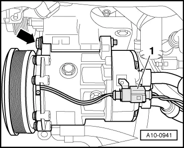
Vehicles with air conditioner:
Important
The air conditioner refrigerant circuit must not be opened.
|
 |
|
|
All models:
|
 |
|
|
 |
|
|
Vehicles with engine code AXR:
|
 |
|
|
All models:
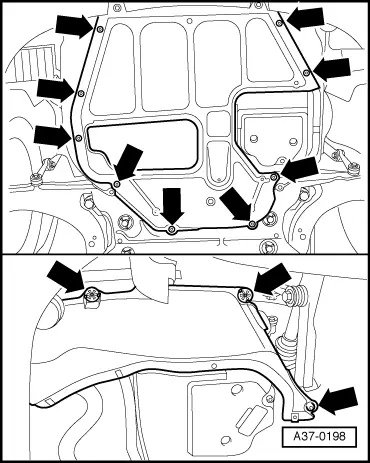
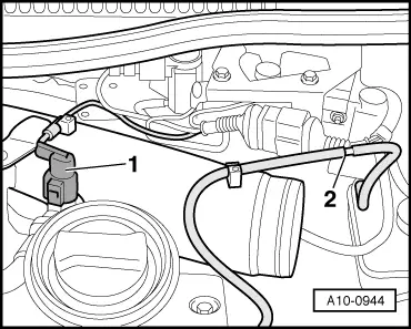
Note: Illustration shows an engine with code ASZ, ATD. |
 |
|
Note: Illustration shows an engine with code ASZ, ATD. |
 |
|
|
 |
|
|
 |
|
|
Vehicles with engine code ATD, AXR:
|
 |
|
|
All models:
|
 |
|
|
 |
|
|
 |
|
|
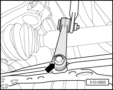
Note: The isolating element in front exhaust pipe must not be deflected more than 10 °to avoid damage.
|
 |
|
|
 |
|
|
 |
|
|
 |
|
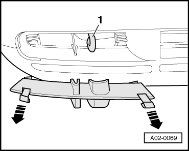
Note: Protect bumper from scratches by using an adhesive tape.
|
 |
|
|
|
|
|
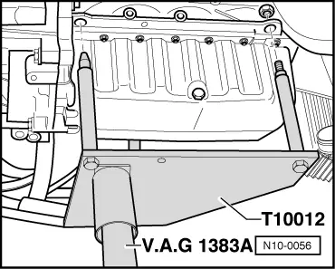
Note: To unscrew bolts for assembly mounting use stepladder VAS 5085.
|
|
|
Notes:
|