audi Workshop Repair Guides

Audi Workshop Service and Repair Manuals

Radiator and radiator fan - Assembly overview > < Removing and installing, checking coolant thermostat
4-cyl TDI®-Engine, Mechanical Components
Removing and installing parts of the cooling system
Removing and installing coolant pipe
 
W00-0464

Special tools and workshop equipment required

  • ◆ V.A.G 1921

 
A10-0933

Removing

  • ‒ Drain coolant => Page 19-7.
  • ‒ → Remove air duct hose -1- from air duct pipe.
  • ‒ Detach connector of air mass meter -3-.
  • ‒ Unscrew bolts -4- and -5-.
  • ‒ Remove vent hose -2- off air cleaner housing.
  • ‒ Remove air cleaner housing.
 
A21-0188
  • ‒ → Detach connector-4-.
  • ‒ Detach vacuum hose -3- at cutting point.
  • ‒ Unscrew bolts -1- and -2-.
  • ‒ Put solenoid valve brackets to side with hoses connected.

 
A10-0416

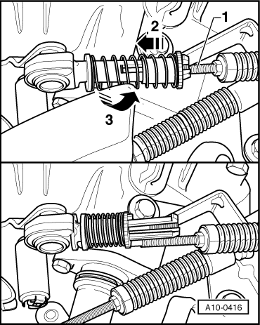
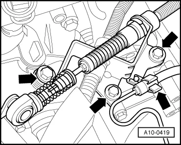
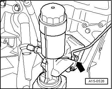
Vehicles with manual gearbox:

Detach both gear selector cables from gearbox as follows:

  • ‒ → Mark installation position of thread rods -1- of both gear selector cables with a waterproof felt-tip pen.
  • ‒ Pull the spring with the knurled piece in direction of arrow -2- towards spherical joint and then turn knurled piece clockwise to secure in engaged position -arrow 3-.
  • ‒ Detach both gear selector cables.
 
A10-0419
  • ‒ → Remove cable counterhold from gearbox and place to one side
    -arrows-.

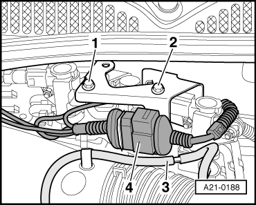
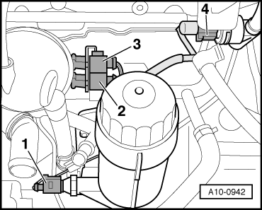
Vehicles with engine code ATD, AXR:
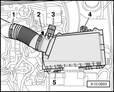
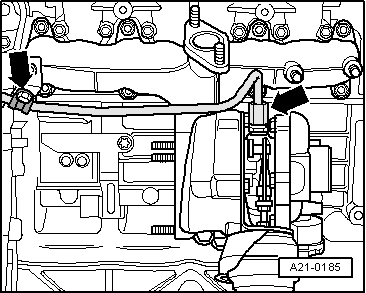
  • ‒ Unclip the clutch slave cylinder hose at the cable support bracket.

 
A19-0337

All models:

  • ‒ Remove all hoses from coolant pipe.
  • ‒ → Disconnect lower coolant hose -1- at coolant connection.
  • ‒ Unplug connector -2- at coolant temperature sender -G62.
 
A10-0924
  • ‒ Detach the heat protection sleeve at the speedometer sender -G22.
  • ‒ → Detach connector -arrow- from speedometer sender -G22 from gearbox.
  • ‒ Lay wiring aside.

 
A15-0793

Vehicles with engine code AXR:

  • ‒ → Disconnect coolant hoses -1- and -2- at exhaust gas recirculation cooler.
 
A21-0185

All models:

  • ‒ → Unscrew oil feed line from turbocharger and exhaust manifold
    -arrows-.

 
A15-0528
  • ‒ → Unscrew oil feed line from oil filter bracket -arrow- and also at coolant pipe and lay line aside.
 
A10-0942
  • ‒ Unplug connector console from glow plugs.
  • ‒ → Detach the following connectors:
  •     1 -    Oil pressure switch -F1
  •     2 -    Hall sender -G40
  •     3 -    Engine speed sender -G28
  •     4 -    Fuel temperature sender -G81
  • ‒ Detach connectors -2- and -3- from the bracket at coolant pipe.

 
A19-0029
  • ‒ Lay aside wiring at air coolant pipe.
  • ‒ Remove the coolant pipe from cylinder block.
  • ‒ → Take coolant pipe -2- from connection.
 
A19-0029

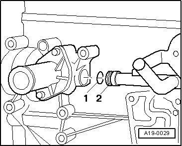
Installing

Installation is carried out in the reverse order; note the following:

Note:

Replace seals and gaskets.

  • ‒ Before installing, clean and smooth down sealing surface for O-ring.
  • ‒ → Coat new O-ring -1- with G 012 A8 D and push onto coolant pipe -2-.
  • ‒ Push coolant pipe into opening in cylinder block.
  • ‒ Top up coolant => Page 19-10.

Tightening torques

Component

Nm

Coolant pipe to cylinder block

M7

15

M10

25

Oil line to oil filter flange

25

Oil supply pipe to turbocharger

30

Radiator and radiator fan - Assembly overview > < Removing and installing, checking coolant thermostat