|
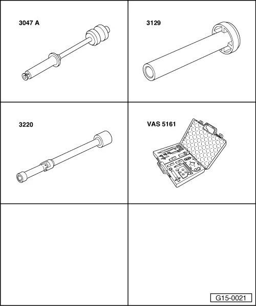
Special tools and workshop equipment required
-
◆ Puller 3047 A
-
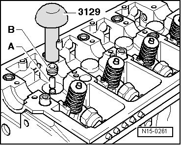
◆ Fitting tool 3129
-
◆ Flexible-head spanner 3220
-
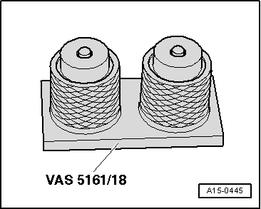
◆ Disassembly and assembly tool VAS 5161
Removing
-
● Cylinder head installed
Note:
When cylinder head was removed the valve stem seals can be replaced when using special tool 2037.
-
‒ Removing camshaft => page 15-100.
-
‒ Remove camshaft bearing shells from cylinder head.
Notes:
-
◆ Make sure that the camshaft bearing shells are not interchanged.
-
◆ Mark allocation of camshaft bearing shells on rear with a waterproof felt-tip pen.
-
◆ Make sure that the bucket tappets are not interchanged.
-
◆ Mark allocation of bucket tappets on rear with a waterproof felt-tip pen.
-
‒ Remove the bucket tappets from guides and put them down with the contact surface downwards.
|