audi Workshop Repair Guides

Audi Workshop Service and Repair Manuals

Checking piston projection at TDC > < Cracked conrods
4-cyl TDI®-Engine, Mechanical Components
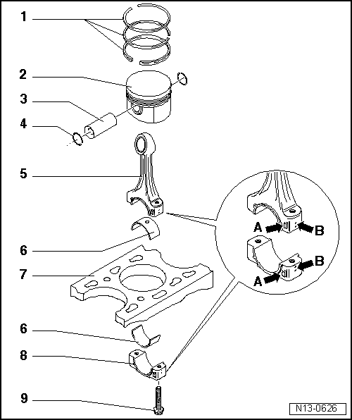
Dismantling and assembling pistons and conrods
Sawn conrods
 
N13-0626

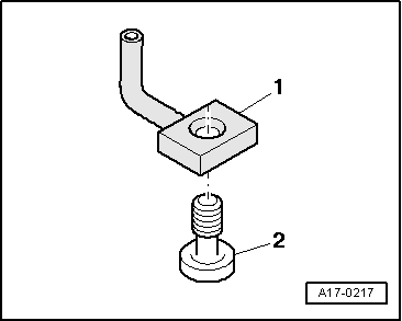
Note:

Oil spray jet and pressure relief valve

=> Fig.13-116

  • Piston rings
    • ◆ Offset gaps by 120°
    • ◆ Remove and install with piston ring pliers.
    • ◆ Marking "TOP" or inscription must face piston crown.
    • ◆ Checking ring gap
      => Fig.13-113
    • ◆ Checking ring to groove play
      => Fig.13-113
 
N13-0626
  • Piston
    • ◆ Mark installation position and cylinder number.
    • ◆ Installation position and arrangement of piston/cylinder
      => Fig.13-114
    • ◆ If cracking is visible on piston skirt, replace piston
    • ◆ Arrow on piston crown points to pulley end.
    • ◆ Install using piston ring clamp.
    • ◆ Checking piston projection at TDC =>Page 13-117
    • ◆ Piston and cylinder dimensions
      =>Page 13-119
    • ◆ Checking => Fig.13-115
 
N13-0626
  • Piston pin
    • ◆ If difficult to remove, heat piston to approx. 60°C.
    • ◆ Remove and install with VW 222a
  • Circlip
  • Conrod
    • ◆ Only renew as a set
    • ◆ Mark cylinder number B
    • ◆ Installation position:
      Markings A face towards pulley side
 
N13-0626
  • Bearing shell
    • ◆ Installation position
      => Fig.13-116
    • ◆ Do not interchange used bearing shells (mark).
    • ◆ Note versions:
      upper bearing shell (facing piston) made of more wear-resistant material
      Characteristic with new bearing shells:
      black line on running surface near cutting point
    • ◆ Install bearing shells centrally
    • ◆ Ensure tight fit
    • ◆ Axial play:
      Wear limit: 0.37 mm
    • ◆ Check radial play with Plastigage:
      Wear limit: 0.08 mm
      Do not rotate crankshaft when checking radial play
 
N13-0626
  • Cylinder block
    • ◆ Checking cylinder bore
      => Fig.13-115
    • ◆ Piston and cylinder dimensions
      =>Page 13-119
  • Conrod bearing cap
    • ◆ Mark cylinder number B
    • ◆ Installation position:
      Markings A face towards pulley side
  • Conrod bolt - 30 Nm + 90° (1/4 turn) further
    • ◆ Replacing
    • ◆ Oil threads and contact surface
    • ◆ To measure radial play tighten to 30 Nm but not further
 
V13-0016

→ Fig. 1    Checking piston ring gap

  • ‒ Push ring into cylinder seated squarely on cylinder wall from top down up to approx. 15 mm before bottom edge of cylinder. Use a piston without rings.

Piston ring
Dimensions in mm

New

Wear limit

1st compression ring

0.25...0.40

1.0

2nd compression ring

0.25...0.40

1.0

Oil scraper ring

0.25...0.50

1.0

 
V13-0687

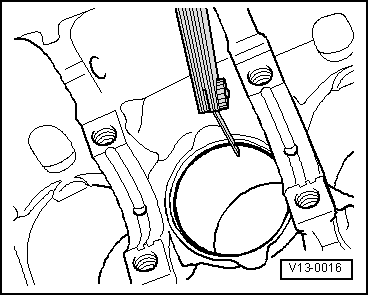
→ Fig. 2    Checking ring to groove play

  • ‒ Clean groove before checking play.

Piston ring
Dimensions in mm

New

Wear limit

1st compression ring

0.06...0.09

0.25

2nd compression ring

0.05...0.08

0.25

Oil scraper ring

0.03...0.06

0.15

 
V13-1204

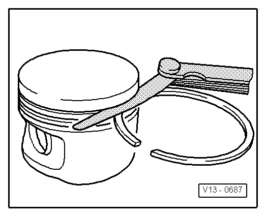
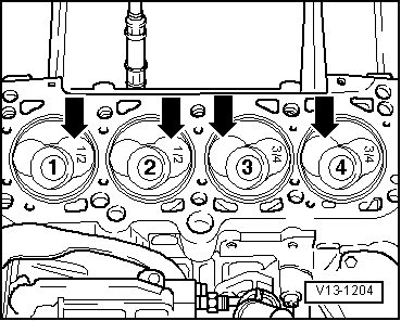
→ Fig.3    Piston installation position and arrangement of piston/cylinder

  • ‒ Mark installation position and allocation on inside of piston (not on piston crown) with electric pen or felt-tip pen.

Pistons in cylinder 1 and 2:

Large valve pocket for inlet valve towards flywheel side -arrows-

Pistons in cylinder 3 and 4:

Large valve pocket for inlet valve towards pulley side -arrows-

Note:

On new pistons the cylinder numbers are marked in colour on the piston crowns.

  • ◆ Pistons for cylinder 1 and 2:
    are marked 1/2
  • ◆ Pistons for cylinder 3 and 4:
    are marked 3/4
 
V13-0010

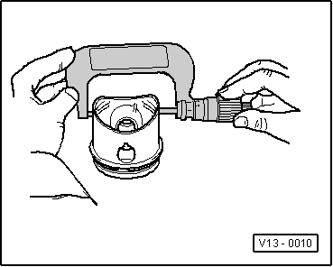
→ Fig. 4    Checking piston

  • ‒ Measure approx. 10 mm from the lower edge, offset by 90° to the piston pin axis.
    • ‒ Permissible deviation from nominal dimension:
      no more than 0.04 mm.

 
V13-0280

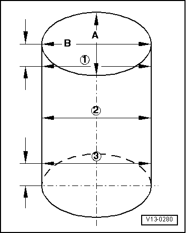
→ Fig. 5    Checking cylinder bores

Special tools and workshop equipment required

  • ◆ Use internal dial gauge 50...100 mm.
  • ‒ Take measurements at 3 positions in both lateral direction -A- and longitudinal direction -B-.
    • ‒ Permissible deviation from nominal dimension:
      no more than 0.10 mm.
 
A13-0360

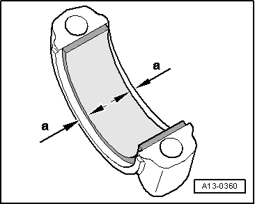
→ Fig.6    Installation position of bearing shell

  • ‒ Install bearing shells centrally into conrod or into conrod bearing cap.
    • ‒ Dimension a = 2.5 mm

 
A17-0217

→ Fig.7    Oil spray jet and pressure relief valve

  •     1 -    Oil spray jet (for cooling of piston)
  •     2 -    Bolt with pressure relief valve - 27 Nm
    • ‒ Opening pressure 1.3 ... 1.6 bar

Checking piston projection at TDC > < Cracked conrods