audi Workshop Repair Guides

Audi Workshop Service and Repair Manuals

Crankshaft dimensions > < Removing and installing dual mass flywheel/drive plate
4-cyl TDI®-Engine, Mechanical Components
Removing and installing crankshaft
 
A13-0382

Note:

When working on the engine, it should be secured to the repair stand using engine bracket VW 540 => Page 10-73.

  • Bearing shell
    • ◆ For cylinder block with oil groove
    • ◆ Do not interchange used bearing shells (mark).
  • Chain sprocket
    • ◆ For oil pump drive chain
    • ◆ Replacing => Page 13-101.
  • Bearing shell
    • ◆ For bearing cap without oil groove
    • ◆ Do not interchange used bearing shells (mark).
 
A13-0382
  • Thrust washers
    • ◆ For mounting 3
    • ◆ Different types for cylinder block and bearing cap
    • ◆ Note fixing arrangement
  • 65 Nm + 90° (1/4 turn) further
    • ◆ Replacing
    • ◆ When measuring radial play of crankshaft, tighten to 65 Nm but do not turn further.
  • Bearing cap
    • ◆ Bearing cap 1: Pulley end
    • ◆ Bearing cap 3 with recesses for thrust washers
    • ◆ Bearing shell retaining lugs (cylinder block/bearing cap) must be on the same side.
 
A13-0382
  • 10 Nm + 90° (1/4 turn) further
    • ◆ Replacing
    • ◆ After each loosening of bolts replace sender wheel
      => Fig.13-98
  • Sender wheel
    • ◆ For engine speed sender -G28
    • ◆ Can only be installed in one position. Holes are off set
    • ◆ Always renew sender wheel if securing bolts have been unscrewed.
    • ◆ Removing and installing
      => Fig.13-98
  • Dowel pin
    • ◆ Check projection from crankshaft => Fig.13-99
 
A13-0382
  • Crankshaft
    • ◆ Axial play new: 0.07 ... 0.23 mm
      Wear limit: 0.30 mm
    • ◆ Check radial play with Plastigage
      New: 0.02 ... 0.04 mm
      Wear limit: 0.15 mm
    • ◆ Do not rotate the crankshaft when checking the radial play.
    • ◆ Crankshaft dimensions
      =>Page 13-100
 
A13-0150

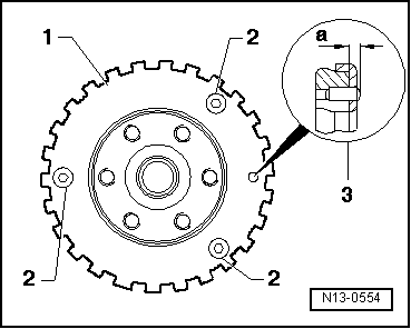
→ Fig.1    Removing and installing sender wheel

  • ‒ Always renew sender wheel -2- if securing bolts -1- have been unscrewed.

Notes:

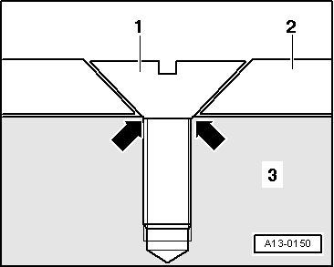
  • ◆ If the securing bolts are tightened a second time, the seats for the countersunk bolt heads in the sender wheel will be distorted to such an extent that the bolt heads will come into direct contact with the crankshaft -3- (- arrows -) and the sender wheel will only fit loosely under the bolts.
  • ◆ The mounting holes are asymmetrically spaced, so it is only possible to install the sender wheel in one position.

Tightening torque

Component

Nm

Sender wheel to crankshaft

10 + 90° 1)2)

    1)    Replace bolts

    2)    90°corresponds to a quarter of a turn

 
N13-0554

→ Fig. 2    Checking projection of dowel sleeve from crankshaft

Projection of dowel sleeve -3- from crankshaft

  • ◆ a =2.5 ... 3.0 mm

Crankshaft dimensions > < Removing and installing dual mass flywheel/drive plate