audi Workshop Repair Guides

Audi Workshop Service and Repair Manuals

Toothed belt drive with friction-absorbing tensioning roller - Assembly overview > < Toothed belt drive with hydraulically damped tensioning roller - Assembly overview
4-cyl TDI®-Engine, Mechanical Components
Toothed belt drive with hydraulically damped tensioning roller - Assembly overview
Removing and installing toothed belt
 
G13-0030

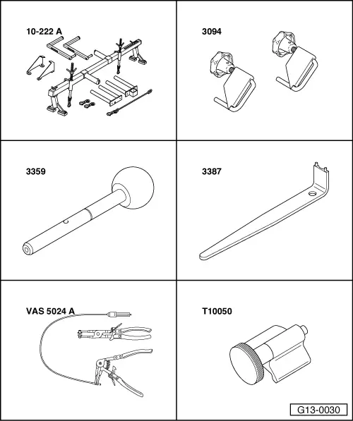
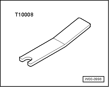
Special tools and workshop equipment required

  • ◆ Support bar 10-222A
  • ◆ Hose clamps 3094
  • ◆ Mandrel 3359
  • ◆ Pin wrench 3387
  • ◆ VAS 5024 A
  • ◆ Crankshaft stop T10050
 
W00-0998
  • ◆ Securing plate T10008
  • ◆ Drill, ø4 mm
  • ◆ Locking compound

=> Parts List

 
A13-0374

Removing

  • ● Engine in vehicle
  • ‒ Remove ribbed belt => Page 13-10
  • ‒ → Remove tensioner for ribbed belt cover -arrows-.
 
A13-0385
  • ‒ → Disconnect hose -5- to air cleaner housing.
  • ‒ Disconnect crankcase vent pipe -6- from air duct hose.
  • ‒ If installed, detach connector for heating resistor (crankcase venting) -N79 -Item 3-.
  • ‒ Release spring clamp on turbocharger using VAS 5024 A.

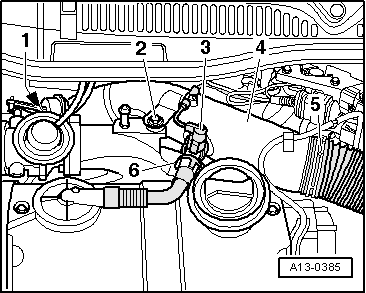
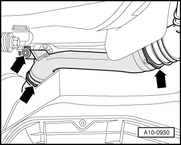
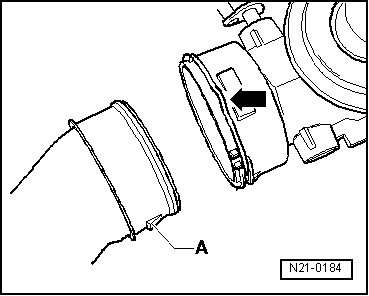
Note:

For vehicles with four-wheel drive, the spring clamp is not accessible from above. To release the spring clamp, remove the air duct pipe from the right longitudinal member and the centre and right noise insulation.

  • ‒ Set aside the vacuum hoses.
  • ‒ Unscrew bolts -1- and -2- and remove air duct pipe -4-.
 
A13-0386
  • ‒ → Attach support bar 10-222 A onto screwed edge of wing and attach spindle in right engine lifting eye.
  • ‒ Lift engine slightly with spindle of engine support bracket 10-222 A.

 
A13-0387
  • ‒ → Mark fuel feed pipe and fuel return pipe -3- and remove from fuel filter.
  • ‒ Unplug connector -arrow-.
  • ‒ Unbolt coolant expansion tank -1- for coolant. Do not detach hoses.
  • ‒ Unscrew refill reservoir -2- for power steering.
  • ‒ Clamp off hose to steering box using hose clamp 3094.
  • ‒ Detach refill reservoir line.

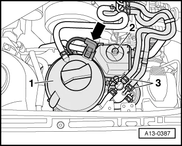
Note:

Close opening at refill reservoir with plug.

 
N13-0221
  • ‒ Remove coolant expansion tank and refill reservoir for power steering towards front.
  • ‒ → Unbolt brace between engine console and chassis -arrows-.
  • ‒ Unbolt engine console from engine support and from chassis
    -arrows-.
  • ‒ Take out engine console.

 
A13-0394
  • ‒ → Remove the upper toothed belt guard -arrows-.
 
A10-0930
  • ‒ → Remove air duct pipe from right longitudinal member -arrows-.

 
A37-0198
  • ‒ → Remove noise insulation in centre and on right -arrows-.
 
A13-0356
  • ‒ → Unbolt vibration damper.

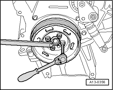
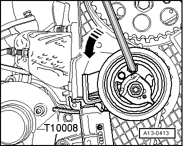
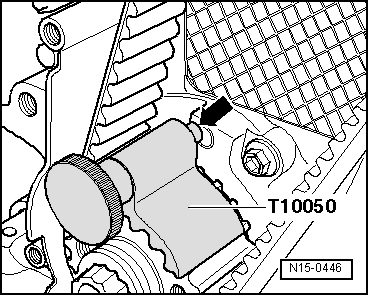
Note:

To loosen and tighten the vibration damper counterhold with ring spanner on central bolt.

 
A13-0171
  • ‒ → Unbolt bottom and centre section of toothed belt guard -arrows-.
 
A13-0505
  • ‒ → Remove bolts for engine support -1 ... 3- and swivel engine support slightly to the rear.

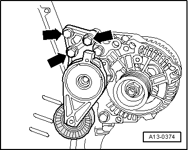
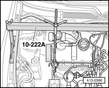
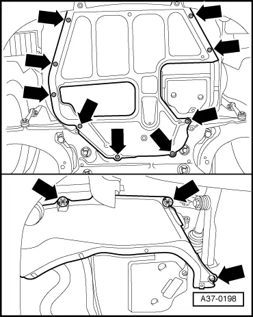
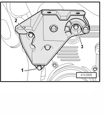
Note:

To remove the bolts for the engine support, raise or lower the engine slightly as necessary using the spindles on engine support bracket 10-222A.

 
A13-0349
Important
The engine must only be turned at the crankshaft, in the direction of engine rotation (clockwise).
  • ‒ Set the crankshaft to TDC for cylinder No. 1.

Notes:

  • ◆ → The space between the two lugs -1- on sender wheel of camshaft must align with marking "4Z" -Item 2- on rear toothed belt guard.
  • ◆ The illustration shows the toothed belt camshaft sprocket without toothed belt.
  • ‒ Lock the hub with mandrel 3359.
 
A13-0350
  • ‒ → Lock the crankshaft toothed belt sprocket with crankshaft stop T10050.

Notes:

  • ◆ The markings on the toothed belt sprocket -2- and crankshaft stop -1- must align. The journal of the crankshaft stop must engage in the bore of the sealing flange.
  • ◆ The crankshaft stop can only be pushed from the front onto the toothed belt sprocket due to the splines.

 
A13-0358
  • ‒ Mark running direction of belt with chalk or felt pen.
  • ‒ → Loosen the bolts -arrows- at the camshaft sprocket.
 
A13-0413
  • ‒ → Insert an Allen key into hexagon until limit stop and thus push the tensioning roller anti- clockwise -direction of arrow- until the tensioner of the toothed belt can be locked with the connecting pin T10008.

Notes:

  • ◆ Insert Allen key until limit stop to avoid damage.
  • ◆ The toothed belt tensioner is oil damped, and can only be compressed slowly by applying continuous pressure.

 
A15-0598
  • ‒ Loosen securing nut of tensioner.
  • ‒ → Unscrew bolts -arrows- of toothed belt tensioner and remove.
  • ‒ Remove toothed belt first from coolant pump and then from the remaining gears.

Installing (adjusting valve timing)

  • ● Camshaft locked with mandrel 3359.
  • ● Crankshaft locked with crankshaft stop T10050.
  • ● Toothed belt tensioner is locked with securing plate T10008.

Notes:

  • ◆ Adjustments to the toothed belt may only be performed when engine is cold.
  • ◆ When turning the camshaft, the crankshaft must not be at TDC for any piston. Danger of damage to valves/piston crown.
 
A13-0358
  • ‒ → Loosely secure the bolts -arrow-.
    • ‒ The camshaft sprocket should be just able to turn on the hub and must not tilt.
  • ‒ Turn the camshaft sprocket in its longitudinal holes clockwise, as far as possible.
  • ‒ Attach toothed belt to camshaft sprocket, tensioning roller, toothed belt sprocket crankshaft and finally to toothed belt sprocket coolant pump.
  • ‒ Install tensioner for toothed belt.
 
A13-0359
  • ‒ Adjust toothed belt tension as follows:
  • ‒ → Turn the cam anti-clockwise until limit stop -A- with pin wrench 3387.
  • ‒ Remove securing plate T10008.

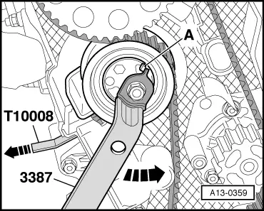
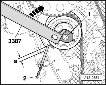
Note:

Special tool Matra V/159 may be used in place of pin wrench 3387.

 
A13-0354
  • ‒ → Slowly release pressure on tensioner clockwise until a ø 4.0 mm drill with -Item 2- can be easily inserted between tensioning lever and tensioner housing.
    • ‒ Dimension a = 4.0 ± 1.0 mm
  • ‒ Hold the tensioning roller in this position and tighten tensioning roller nut -1- to 20 Nm + 45° (1/8 turn).
 
A13-0358
  • ‒ → Tighten the camshaft sprocket bolts -arrows- to 25 Nm.
  • ‒ Remove mandrel 3359 and crankshaft stop T10050.

 
A13-0354
Important
The engine must only be turned at the crankshaft, in the direction of engine rotation (clockwise).
  • ‒ Turn the crankshaft two rotations in the direction of engine rotation until the crankshaft is set to TDC again.
  • ‒ → Check again whether dimension -a- is achieved between tensioning lever and tensioner housing.
    • ‒ Dimension a = 4.0 ± 1.0 mm
  • ‒ If dimension -a- is not achieved, readjust tensioning roller as follows:
  • ‒ Counterhold tensioning roller with pin wrench 3387, loosen nut -1- and slacken counterforce of tensioner -arrow-, until measure -a- has been reached.
    • ‒ Dimension a = 4.0 ± 1.0 mm
  • ‒ Hold the tensioning roller in this position and tighten tensioning roller nut -1- to 20 Nm + 45° (1/8 turn).
 
A13-0350

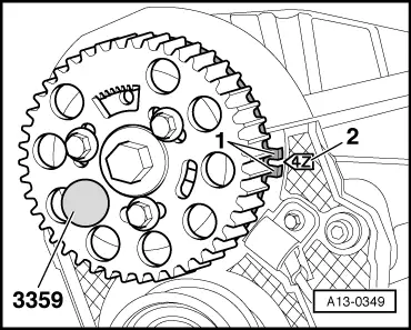
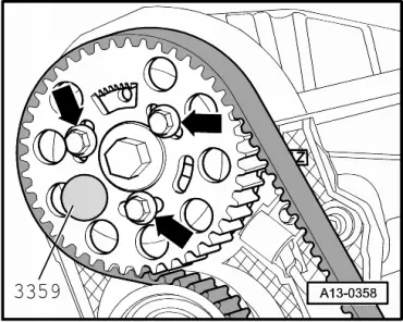
Checking the valve timing

  • ‒ → For checking purposes, lock the crankshaft toothed belt sprocket again using crankshaft stop T10050.

Notes:

  • ◆ The markings on the toothed belt sprocket -2- and crankshaft stop -1- must align. The journal of the crankshaft stop must engage in the bore of the sealing flange.
 
N15-0446
  • ◆ → The pin of the crankshaft stop must engage into the bore of the sealing flange when rotated -arrow-.
  • ◆ If the crankshaft was turned over TDC for cylinder 1, then turn back crankshaft 1/4 turn to position it again to TDC for cylinder 1 in direction of engine rotation.
  • ◆ Corrections against the rotation direction of the engine to adjust the crankshaft stop are not permitted.

 
A13-0349
  • ‒ → Check with mandrel 3359 whether hub can be locked.

Notes:

  • ◆ The space between the two lugs -1- on sender wheel of camshaft must align with marking "4Z" -Item 2- on rear toothed belt guard.
  • ◆ The illustration shows the toothed belt camshaft sprocket without toothed belt.
 
A13-0358

If hub cannot be locked:

  • ‒ → Loosen the securing bolts -arrows- on the camshaft sprocket.
  • ‒ Apply a ring spanner to centre bolt of camshaft.
  • ‒ Turn hub until the mandrel 3359 can be inserted.
  • ‒ Tighten the bolts -arrows- of camshaft sprocket to 25 Nm.
  • ‒ Remove mandrel 3359 and crankshaft stop T10050.
Important
The engine must only be turned at the crankshaft, in the direction of engine rotation (clockwise).
  • ‒ Turn the crankshaft two rotations in the direction of engine rotation until the crankshaft is set to TDC again.
  • ‒ Repeat valve timing checks =>Page 13-38.
  • ‒ Install toothed belt guard (bottom and centre sections).
  • ‒ Install toothed belt guard (top section).
 
A13-0505

The remaining installation steps are carried out in the reverse sequence - note the following points:

→ Secure the engine support as follows:

  • ‒ Remove bolts -1 ... 3-.
  • ‒ Then tighten the bolts -1 ... 3- to 45 Nm.
  • ‒ Install engine console.
  • ‒ Install the vibration damper => Page 13-7.
  • ‒ Adjust engine mounting => Page 10-85.
  • ‒ Install ribbed belt =>Page 13-12.
 
N21-0184
  • ‒ → When installing air duct pipes with connectors, ensure that the securing clip -arrow- engages audibly in the retaining lug -A-.
  • ‒ Install and secure coolant expansion tank and power assisted steering reservoir.

Tightening torques

Component

Nm

Toothed belt tensioning roller to cylinder head


20 + 45° 1)

Camshaft sprocket to hub

25

Lower section of toothed belt guard to cylinder block


10 2)

Toothed belt tensioner to cylinder block


13

Centre section of toothed belt guard to cylinder block


10 2)

Vibration damper to crankshaft sprocket


10 + 90°3)4)

Engine support to cylinder block

45

Engine console to chassis

50

Engine support to engine console

100 3)5)

    1)    45°corresponds to an eighth of a turn

    2)    install using locking compound;
        locking compound

=> Parts List

    3)    Replace bolts

    4)    90°corresponds to a quarter of a turn

    5)    Only tighten to final torque after adjusting the engine mounting=> Page 10-85

Component

Nm

Brace to engine console/chassis


25

Tensioner for ribbed belt tensioner to bracket for auxiliary mechanical units


23

Rear air duct pipe to intake manifold

10

Toothed belt drive with friction-absorbing tensioning roller - Assembly overview > < Toothed belt drive with hydraulically damped tensioning roller - Assembly overview