
A3 Mk1
|
Exhaust gas recirculation system
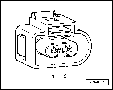
Checking EGR valve -N18
|
 |
|
|
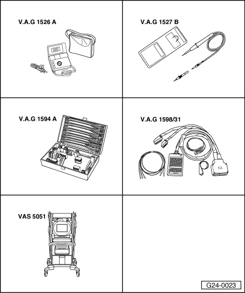
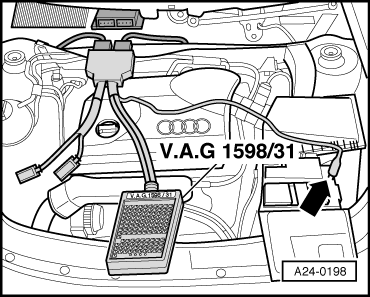
Special tools and workshop equipment required
|
 |
|
|
Checking internal resistance
|
 |
|
|
 |
|
Note: Resistance is in the lower tolerance range at room temperature and in the upper tolerance range when the engine is warm. If specified value is not attained:
|
 |
|
|
Checking power supply
If specified value is not attained:
|
|
|
|
Checking actuation
|
 |
|
|
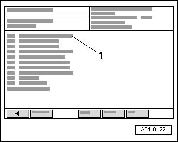
→ Display on VAS 5051:
|
 |
|
|
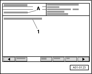
→ Display on VAS 5051:
Note: Voltage testers with a low current consumption continue to glow faintly between actuation from the engine control unit (rather than extinguishing completely) and become much brighter when actuated.
|
 |
|
|
If the LED lamp does not react as described:
=> TDIInjection and Glow Plug System(4-cyl Pump Jet); Repair group 23 Important
To prevent damage to the electronic components, select appropriate measuring range before connecting the measuring cables and observe the test requirements. |
|
||||||
|