audi Workshop Repair Guides

Audi Workshop Service and Repair Manuals

Checking intake manifold pressure sender -G71 > < Hose connection diagram for solenoid valves at bulkhead
4-cyl TDI®-Engine, Mechanical Components
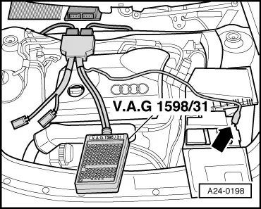
Checking charge air system with turbocharger
Checking solenoid valve for boost pressure limitation -N75
 
A10-0929
  • ‒ → Remove oil dipstick -1- from guide tube.
  • ‒ Remove engine cover -arrows-.
  • ‒ Reinsert dipstick in guide tube.

 
A23-0148

Checking internal resistance

  • ‒ Switch ignition off.
  • ‒ → Unplug connector from boost pressure control solenoid valve -N75 -Item 3-.
 
A23-0149
  • ‒ → Connect multimeter between contacts 1 and 2 to measure resistance.
    • ‒ Specified value: 14...20 ω

If specified value is not attained:

  • ‒ Replace solenoid valve for boost pressure control -N75.

 
A24-0331

Checking power supply

  • ‒ → Connect multimeter between contact 2 and earth to measure voltage.
  • ‒ Switch the ignition on.
    • ‒ Specified value: approx. battery voltage

If specified value is not attained:

  • ‒ Check wiring for open circuit and service if necessary.
 
A24-0331

Checking actuation

  • ‒ → Connect voltage tester V.A.G 1527 B between contacts 1 and 2.
  • ‒ Start final control diagnosis and activate solenoid valve for boost pressure control -N75:

=> TDIInjection and Glow Plug System(4-cyl Pump Jet); Repair group 01; Final control diagnosis

    • ‒ The LED must flash slowly.

Note:

Voltage testers with a low current consumption continue to glow faintly between actuation from the engine control unit (rather than extinguishing completely) and become much brighter when actuated.

 
A24-0198

If the LED lamp does not react as described:

  • ‒ Switch ignition off.
  • ‒ → Connect the V.A.G 1598/31 test box to wiring harness connectors; the engine control unit should not be connected. Attach the earth clip of test box to earth -arrow-.

=> TDIInjection and Glow Plug System(4-cyl Pump Jet); Repair group 23

Important
To prevent damage to the electronic components, select appropriate measuring range before connecting the measuring cables and observe the test requirements.
 
A24-0331
  • ‒ → Check for open circuit and short to positive or earth in the following wiring connections:

Connector
Contact

Test box V.A.G 1598/31
Socket

1

62

  • ‒ Rectify any open/short circuit as necessary.

Checking intake manifold pressure sender -G71 > < Hose connection diagram for solenoid valves at bulkhead