audi Workshop Repair Guides

Audi Workshop Service and Repair Manuals

Connection diagram for boost pressure control -engine code AXR- > < Checking vacuum pressure actuation to turbocharger
4-cyl TDI®-Engine, Mechanical Components
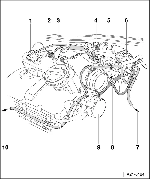
Checking charge air system with turbocharger
Connection diagram for boost pressure control -engine codes ASZ, ATD-
 
A21-0184
  • Intake pipe connection
    • ◆ With mechanical exhaust gas recirculation valve
    • ◆ With intake manifold flap
  • Vacuum unit for intake manifold flap
  • To the vacuum unit for boost pressure control
  • EGR valve 1 -N18
    • ◆ Fitting location: On bulkhead in engine compartment
    • ◆ Hose connection diagram =>Page 21-25
  • Intake manifold flap changeover valve -N239
    • ◆ Fitting location: On bulkhead in engine compartment
    • ◆ Hose connection diagram =>Page 21-25
 
A21-0184
  • Boost pressure control solenoid valve -N75
    • ◆ Fitting location: On bulkhead in engine compartment
    • ◆ Checking => Page 21-27
    • ◆ Hose connection diagram =>Page 21-25
  • Breather pipe
    • ◆ To air cleaner
  • To brake servo
    • ◆ With deviation to vacuum pressure distributor for solenoid valves
  • Tandem pump
  • Vacuum hose
    • ◆ To vacuum unit

Connection diagram for boost pressure control -engine code AXR- > < Checking vacuum pressure actuation to turbocharger